
Mass Production Startup Manual
rv1126b\Getting-Started-Guide
Hardware Heat Dissipation Guidelines
1. Hardware Heat Dissipation Guidelines
1.1 Core Board Heat Sources
The heat sources on the core board are located as shown below. Only the heat dissipation of the main control chip needs to be considered.
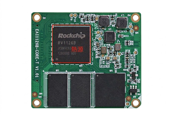
Core Board Heat Source Location
1.2 Heatsink Reference
Currently, a passive cooling method is used. A heatsink designed for the core board is available, and the main control chip is directly connected to the heatsink using thermally conductive silicone.
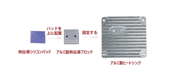
Heatsink Component Structure
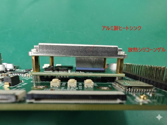
Heatsink Mounted Side View
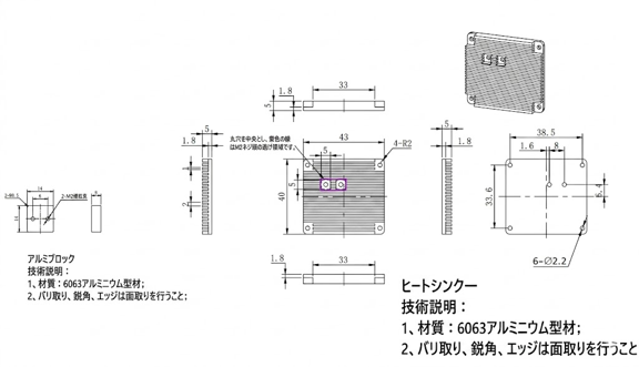
Heatsink Mounted Drawing Set
Using this heatsink can reduce the junction temperature by about 15–16°C. For information about junction temperature, refer to “Application Note / Obtaining System Temperature.”
For heat dissipation design, it is recommended to consider heat dissipation using an aluminum enclosure or similar structure for the entire product, and to maximize the heat dissipation area. This can significantly reduce the system junction temperature.
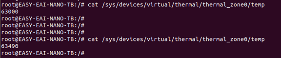
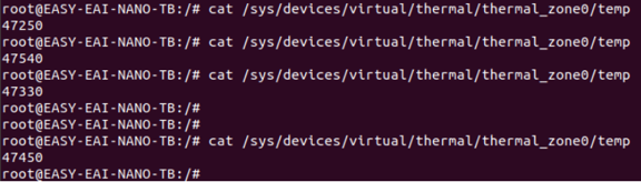
Example for checking the junction temperature:
cat /sys/devices/virtual/thermal/thermal_zone0/tempTest before installing the heatsink: 63.0–63.5°C
Test after installing the heatsink: 47.23–47.84°C
Hardware Mass Production Guidelines
1. Hardware Mass Production Guidelines
1.1 Precautions When Removing
- Since the core board is equipped with many BGA components, frequent insertion and removal are not recommended. If insertion or removal is necessary, exercise great care to prevent poor soldering of components caused by PCB deformation.
- Board-to-board connectors are used, and the signal quality is good, but their service life is limited. The insertion/removal lifetime is 50 cycles.
- To prevent data loss in DDR or eMMC during operation, or device damage, never perform insertion or removal while the power is on (hot plugging).
- Do not use sharp tools when removing the board.
1.2 Surface Mount Technology (SMT) Precautions
The mounting of the core board baseboard connector DF12NA(3.0)-80DP-0.5V(51) must meet the following conditions to ensure good soldering quality.
Recommended stencil thickness: 0.12 mm
Aperture area ratio: 70%
Soldering using a reflow oven or soldering iron must meet the specified temperature conditions.
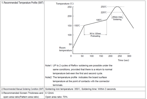
SMT Recommended Temperature Profile
Note: DF12NA is the model with positioning pins, and DF12NC is the model without positioning pins.
1.3 Screw Fastening Guidelines
When fastening screws, use an electric screwdriver. Make sure that the bit is fully engaged with the cross recess of the screw. The torque unit is Kgf.cm.
| Specification | Plastic / Acrylic | Aluminum / Copper | Fiberboard / POM | Low-Carbon Steel / Iron Plate | Stainless Steel |
|---|---|---|---|---|---|
| M2 | 1.0–1.1 | 1.3–1.4 | 1.8–2.0 | 2.0–2.2 | 2.3–2.4 |
| M2.6 | 2.3–2.6 | 2.8–3.2 | 4.0–4.5 | 4.5–5.0 | 5.0–5.5 |
| M3 | 2.8–3.4 | 3.9–4.2 | 5.5–6.0 | 6.0–6.6 | 6.6–7.3 |
| #2-56 (Imperial) | 1.2–1.3 | 1.5–1.6 | 2.1–2.3 | 2.3–2.5 | 2.6–2.9 |
Operating Precautions
- Select appropriate tools and torque settings.
- Before tightening the screw, confirm that the offset of the mounting hole is within 3/4 of the hole diameter.
- Tighten the screw vertically. Angled fastening is prohibited.
- Stop when the screw head is completely flush against the component surface. Be careful not to overtighten.
- The continuous locking time of the electric screwdriver should be within 10 seconds.