
Firmware Writing Manual
1. Firmware Download
After the firmware package is downloaded, extract it and the following folder will be generated.

Extracted folder of the firmware package
There are 2 folders and 2 scripts in the folder.

Folders and scripts in the firmware package
Check the “rockdev” folder. If any content is missing, please download the firmware again. A complete “rockdev” folder contains the following content:
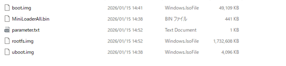
Contents of the rockdev folder
Next, open the tools folder in the order tools → windows → RKDevTool → RKDevTool_Release. You will find the writing tool “RKDevTool.exe”.
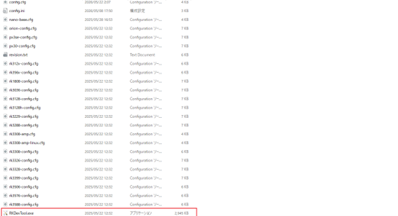
RKDevTool executable file
Double-click to run it. If an error prompt is displayed, it indicates that the firmware package download is incomplete or that a problem occurred during extraction. Please download the firmware package again and extract it again.
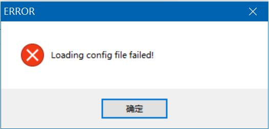
Failed to load configuration file error
When the writing tool starts normally, the interface will be displayed.
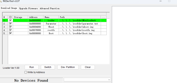
RKDevTool main interface
The detailed description of the image files is as follows.
| Name | Description |
|---|---|
| Loader | Required file for writing. It must be selected for both full writing and partial writing. |
| Parameter | Writing parameters. It contains the official firmware version, boot commands, and other information. |
| Uboot | U-Boot firmware |
| rootfs | File system partition image |
| Boot | Kernel image and device tree file |
2. Hardware Wiring Instructions
Firmware writing uses the ADB (USB 2.0 to Type-C) interface. If Windows does not have a USB-ADB driver, the driver must be installed.
Use a USB 2.0 to Type-C cable to connect the PC and EASY EAI Nano-TB. Do not use a Type-C to Type-C cable because its internal wiring is different.
In addition, you need to [disable the Watchdog].
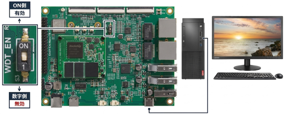
Watchdog disable and wiring instructions
After operating according to the instructions above, connect a 12V/3A power supply.
2.1 Entering Loader Mode
Use the [LOAD button] and the [RESET button].
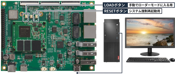
LOAD button and RESET button positions
Make sure the device is powered on. First, press and hold the [LOAD button] and keep it pressed. Then click the [RESET button] once, wait for 3 to 4 seconds, and release the [LOAD button]. The board will then enter LOADER mode.
At this time, if a virtual machine is running, the USB device may be controlled by the virtual machine. In that case, open the virtual machine settings and select “Connect to Host” so that the USB device is connected to the host (PC).

Selecting USB host connection in the virtual machine
When the board successfully enters LOADER mode, it will be recognized by the writing software.
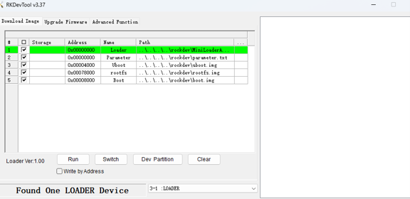
LOADER device detected status
💡 Note: If the writing tool displays “Found one LOADER device” and then immediately returns to “No device found”, it is very likely that the watchdog has not been disabled and the development board has rebooted.
2.2 Troubleshooting Abnormal Situations
If you still cannot enter LOADER mode after completing the operations above, the usual cause is a loose electrical connection between the PC and the board, or the USB driver is not installed correctly, which prevents the USB driver from communicating normally with the main control IC. This causes the board to enter U-Boot.
Solutions:
- Confirm that the USB cable is a USB 2.0 to Type-C cable.
- Confirm that the USB cable has communication capability (the D+ and D- lines are correctly connected).
- Confirm that the communication quality of the USB cable is stable and reliable.
- It is recommended to connect the USB cable directly to the development board without using an extension cable or USB hub (direct connection between the PC and the board).
- It is recommended to use a USB port that comes directly from the desktop PC motherboard (usually a port on the back of the PC case).
- Confirm that the USB driver is installed correctly (refer to “Getting Started Guide / Development Environment Preparation / USB Driver Installation”).
3. Writing Tool Operation
First, make sure the watchdog is turned off. It is off by default at the factory, but the user may have turned it on as needed. Otherwise, the board will reboot immediately after entering Loader mode.
Next, make sure the USB device is not controlled by the virtual machine.

Checking USB control on the Windows side
3.1 Writing Succeeded
Then click the [Run] button. When writing succeeds, a completion message will be displayed. If an exception occurs during writing, handle it according to the specific exception (see the following two failure cases).
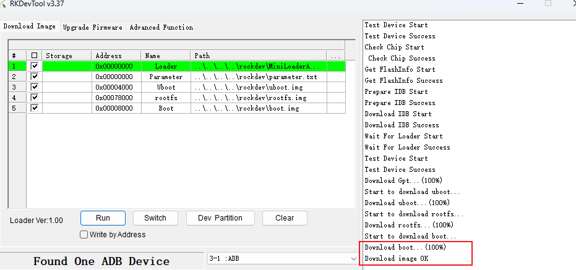
Writing success screen
3.2 Test Device Fail
Causes:
- The driver is not installed correctly.
- The USB device is controlled by the virtual machine.
- The USB cable is unplugged, or the connection is unstable.
Solutions:
- Install the driver correctly.
- Follow “2. Hardware Wiring Instructions” in this document and let Windows control the USB device.
- Reinsert the cable firmly or replace it with another USB cable (using the included standard USB cable is recommended).
After performing the checks above, try writing again.
3.3 Failure During Writing (Download Fail)
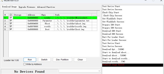
Failure screen during writing
Causes:
- The USB cable was unplugged during the process, or the connection is unstable (high probability).
- The firmware package download is incomplete (low probability).
Solutions:
- Reinsert the cable firmly or replace it with another USB cable (using the included standard USB cable is recommended).
- Download the firmware package again and perform writing again.
4. Entering Maskrom Mode (Recovery from Bricking / Brick Recovery)
After confirming that [writing cannot be performed] even after trying all the methods above, you can rewrite the entire chip by [entering Maskrom mode].
This is a type of safety measure to prevent the system from becoming “bricked” (inoperable).
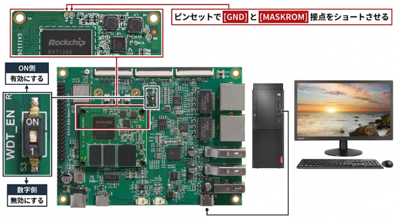
MASKROM short-circuit point position
First, disconnect the power supply and turn off the watchdog. It is off by default at the factory, but if the user has operated it manually before, be sure to turn it off.
Then use a USB 2.0 to Type-C cable to connect the PC and EASY EAI Nano-TB. Do not use a Type-C to Type-C cable because its internal wiring is different.
First, with the power off, short-circuit the [GND] and [MASKROM] contacts and keep them shorted without releasing them. Then connect the 12V power supply, wait for 3 to 4 seconds, and release the contacts. This allows the board to enter MASKROM mode. Be careful about USB control by the virtual machine.
💡 Note: When writing in Maskrom mode, be sure to check the first item, “loader”.
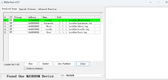
MASKROM device detected status
Click [Run] to start the writing operation.