
Camera, Display, and Audio
1. MIPI-CSI Camera
1.1 Overview of the MIPI Camera
1.1.1 Overview of the MIPI CSI-2 Interface
MIPI (Mobile Industry Processor Interface) is an interface defined by an alliance established in 2003 by companies such as ARM, Nokia, ST, and TI. Its purpose is to standardize internal interfaces in mobile devices such as smartphones, including camera interfaces, display interfaces, and RF/baseband interfaces, thereby reducing device design complexity and improving design flexibility. Under the MIPI Alliance, there are many working groups that define standards for their corresponding devices. These include more than ten groups such as the Camera Working Group, Display Working Group, and High-Speed Multipoint Link Working Group.
MIPI The CSI-2 interface is the second-generation CSI (Camera Serial Interface) standard defined by the Camera Working Group of the MIPI Alliance.
-
Hardware layer: It supports data transmission over up to four virtual channels (lanes). In hardware, each lane is implemented as one pair of differential signal lines (see the schematic). The maximum communication rate of each lane is 2.0 Gbps.
-
Software layer: MIPI The CSI-2 protocol stack is mainly composed of the application layer, protocol layer, and physical layer. The protocol layer is further divided into the pixel/byte packing and unpacking layer, the low-level protocol layer, and the lane management layer.
1.1.2 Introduction to Hardware Interface Resources
The EASY EAI Nano-TB development board provides two MIPI CSI-2 interfaces. Four lanes are routed out from each interface. The location definitions are as follows.
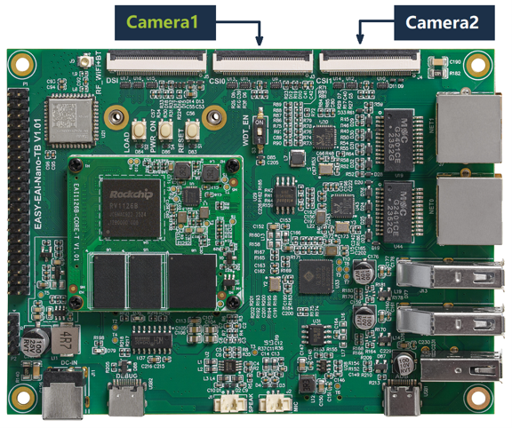
Introduction to Hardware Interface Resources
EASY EAI Nano-TB is used with the IMX415 monocular camera by default. A 0.5 mm-pitch 40-pin FPC reverse cable is also included.
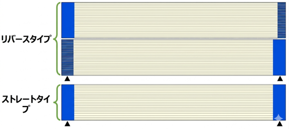
Introduction to Hardware Interface Resources
-
Reverse cable: The blue plastic stiffeners (identification marks) at the two ends are not on the same side.
-
Straight cable: The blue plastic stiffeners at the two ends are on the same side.
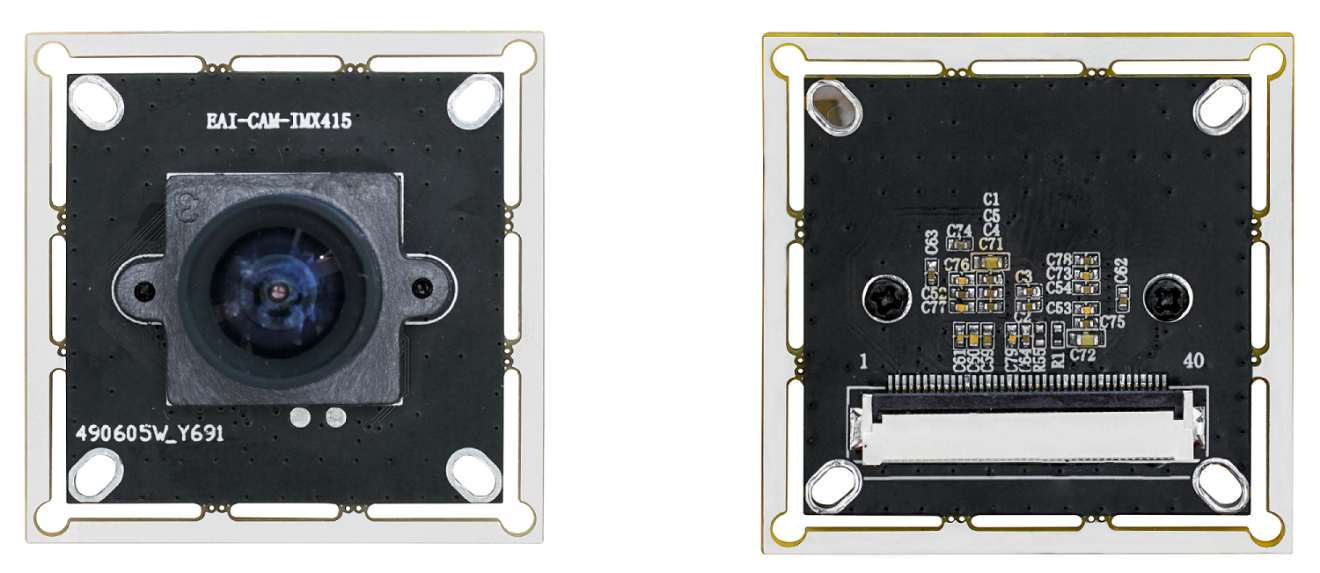
Introduction to Hardware Interface Resources
1.1.3 Wiring Procedure
-
Be sure to perform wiring only when the power is turned off.
-
Use a reverse cable to connect the IMX415 camera to the Camera1 interface.
💡 Note: If the wrong cable type is used, the camera or core board may be burned out. Please be careful when wiring.)
- Make sure the connector lock and the blue plastic identification mark on the FPC cable are on the same side. See the figure below for details.
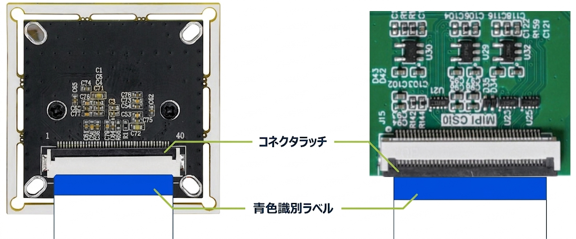
Wiring Procedure
1.1.4 Checking Device Status
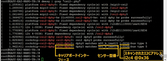
dmesg command to check whether the MIPI-CSI2 interface module is operating normally.
dmesg \| grep "csi2-.phy"When the camera is mounted properly, the output is as follows. The log shows the following information:
-
A camera with sensor model imx415 is connected to the dphy0 interface, and its MIPI-CSI2 address is 1-0036.
-
A camera with sensor model imx415 is connected to the dphy3 interface, and its MIPI-CSI2 address is 4-0036.
Checking Device Status
If the target camera node is not displayed, check whether the FPC cable is connected correctly. Verify that the cable is connected as described in “1.3 Wiring Procedure”.
1.1.5 Searching for Available Device Nodes
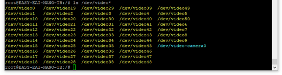
On the Rockchip platform, more than 20 video nodes are allocated for one MIPI-CSI interface (the number generated depends on the device tree definition). See the figure below.
Searching for Available Device Nodes
💡 Note: CSI0 does not necessarily correspond to video0 through video24. Nodes are generated according to the actual device tree configuration.
In addition, the nodes corresponding to MIPI-CSI cameras are fixed when the kernel device tree is modified. In other words, once the number of MIPI-CSI cameras is configured in the kernel, the number of generated video nodes does not change dynamically according to whether actual MIPI-CSI cameras are connected.
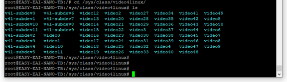
Therefore, users need to determine what device information these nodes correspond to. In the Linux v4l2 framework, the description information for these nodes is collected under the /sys/class/video4linux/ directory.
Searching for Available Device Nodes
Enter any directory, for example video22.

Searching for Available Device Nodes
You can use the cat command to check the contents of this name file. In the Rockchip chip definition, if this name is mainpath or selfpath, video22 is an available node. Run the following command from any directory in the terminal to quickly scan the name descriptions of all nodes.
grep "mainpath" /sys/class/video4linux/video\*/name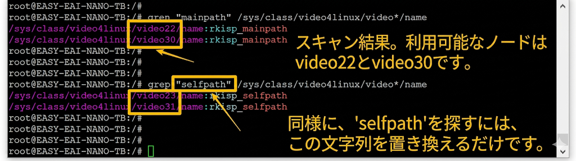
Searching for Available Device Nodes
From the scan result, /dev/video22 and /dev/video23 can be identified as the available nodes of MIPI-CSI0.
1.2. Quick Start
1.2.1 Preparing the Development Environment
On the Ubuntu system on the PC side, run the run script to enter the EASY-EAI compilation environment. The details are as follows.
cd ~/develop_environment./run.sh 22041.2.2 Downloading Source Code and Compiling the Sample
First, run the following command in the background terminal of the virtual machine to create a management directory for the peripheral sample source code:
cd /optmkdir -p EASY-EAI-Nano-TB/demoFor example, download the sample program to “PC\D:”. There is no specific requirement; any location chosen by the user is acceptable.
Then copy the downloaded sample to the file system of the virtual machine.
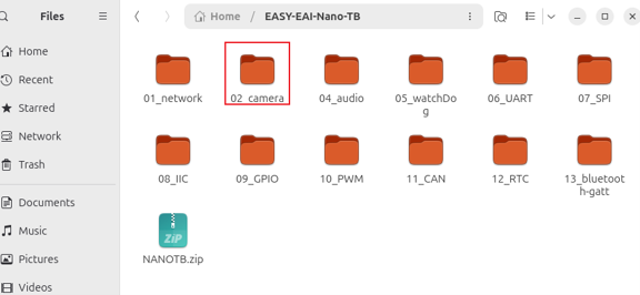
Downloading Source Code and Compiling the Sample
Finally, go to the corresponding sample directory and execute the compilation operation. The specific commands are as follows:
cd EASY-EAI-Nano-TB/demo/02_camera./build.sh💡 Note: Because the dependent libraries are located on the board, the /mnt mount must be maintained during cross-compilation.
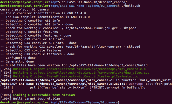
Downloading Source Code and Compiling the Sample
1.2.3 Running the Sample
Access the board backend through serial-port debugging or SSH, and go to the directory where the sample is located:
cd /userdata
Running the Sample
The command for running the sample is as follows:
./test-mipiCam 221.2.4 Execution Result
The execution result is shown in the figure.
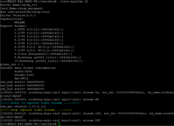
Execution Result
After the sample finishes running, an image file named photo containing raw video data is generated in the /tmp directory. Return to the virtual machine, open a new terminal window, and use the scp command to copy the image to the local machine.

Execution Result
Then use the mplayer command to display the copied photo file.
mplayer -demuxer rawvideo -rawvideo w=1920:h=1080:format=bgr24 photo -loop 0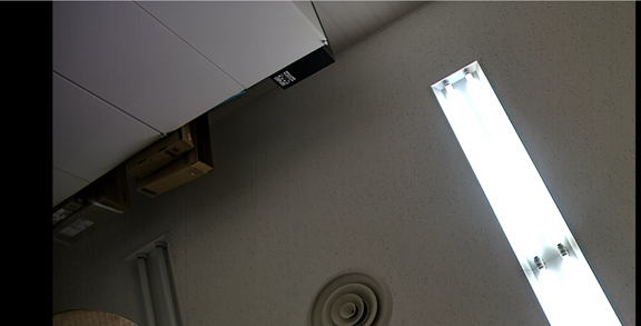
Execution Result
Because the default resolution of the sample is 1920x1080, set the w and h parameters to 1920 and 1080 respectively. If the image is not displayed correctly, the resolution may not match your camera, so you need to adjust the resolution in mipicamera_init(), for example to 1280x720.
1.3 MIPI Camera Test Case
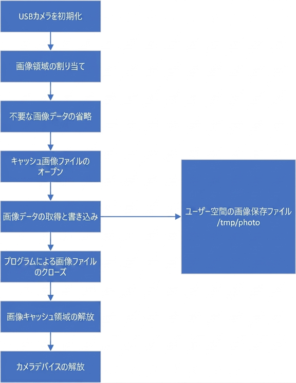
The sample code path is 02_camera/test-mipiCam/main.c. The logic flow of the MIPI Camera API test case code is shown in the figure.
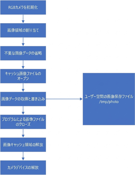
MIPI Camera Test Case
1.3.1 Source Code Description
int main(int argc, char **argv) {    int ret = 0;    if(1 == argc){        printf("\nerr: Missing parameter!\n");        printf("================= [usage] ==================\n");        printf("example:\n");        printf("\t%s <22/30>\n", argv[0]);        printf("--------------------------------------------\n");        return 0;    }
    char *pbuf = NULL;    int skip = 0;    FILE *fp = NULL;
    int cameraIndex = atoi(argv[1]); // Usually video22    ret = mipicamera_init(cameraIndex, CAMERA_WIDTH, CAMERA_HEIGHT, 0);    if (ret) {        printf("error: %s, %d\n", __func__, __LINE__);        goto exit3;    }
    pbuf = (char *)malloc(IMAGE_SIZE);    if (!pbuf) {        printf("error: %s, %d\n", __func__, __LINE__);        ret = -1;        goto exit2;    }
    // Skip the first 10 frames to stabilize exposure and white balance    skip = 10;    while(skip--) {        ret = mipicamera_getframe(cameraIndex, pbuf);        if (ret) {            printf("error: %s, %d\n", __func__, __LINE__);            goto exit1;        }    }
    /* tips: In the Ubuntu environment, you can use mplayer to display the captured image     *  mplayer -demuxer rawvideo -rawvideo w=1920:h=1080:format=bgr24 photo -loop 0    */    fp = fopen("/tmp/photo", "w");    if (!fp) {        printf("error: %s, %d\n", __func__, __LINE__);        ret = -1;        goto exit2;    }    fwrite(pbuf, 1, IMAGE_SIZE, fp);    fclose(fp);
exit1:    free(pbuf);    pbuf = NULL;
exit2:    mipicamera_exit(cameraIndex);
exit3:    return ret;}
In the code, mipicamera_init(), mipicamera_getframe(), and mipicamera_exit() are wrapper functions that simplify calls to the v4l2 interface. The specific implementation is described in 02_camera/commonApi/mipi_camera.c.
2 USB Camera
2.1 USB Overview
USB (Universal Serial Bus) is a general-purpose standard interface commonly used for communication between electronic devices. As a high-speed serial bus, USB can meet the requirements of application environments that require high-speed data transmission. It offers advantages such as easy power supply (bus-powered support), easy installation and configuration (plug-and-play and hot-swap support), easy port expansion (up to 127 peripherals can be expanded through hubs), multiple transfer methods (four transfer modes), and excellent compatibility (backward compatibility after product upgrades).
2.1.1 Introduction to EASY EAI Nano-TB USB Resources
The EASY EAI Nano-TB has one USB3.0 HOST channel, which is expanded through a USB hub chip into two USB3.0 HOST interfaces. It also provides one directly routed USB2.0 HOST interface.
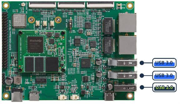
Introduction to EASY EAI Nano-TB USB Resources
2.1.2 USB Camera Connection Procedure
In general, it is recommended to connect only one USB camera.
If multiple USB cameras need to be connected, you may consider using a hub to expand to multi-port USB. In theory, up to 127 devices can be expanded. However, when connecting multiple USB cameras in practice, USB bandwidth, the number of USB hub tiers (the maximum tier count is 7 including the RootHub), and duplicate device ID issues must be considered. Therefore, this type of connection is not recommended unless it is absolutely necessary.
💡 Note: USB supports hot swapping, but when plugging and unplugging devices while the baseboard has no protective enclosure, it is easy to touch components on the baseboard, and nearby metal parts may cause a short circuit. Therefore, it is recommended to plug and unplug peripherals only when the power is completely turned off.
2.1.3 USB Device Connection Management
After physically connecting a USB camera or USB hub, you need to confirm whether these USB devices are correctly recognized by the system. Use the lsusb command for this.
lsusb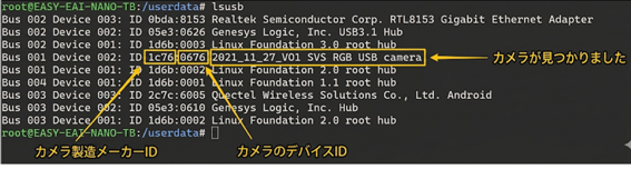
USB Device Connection Management
In the file system, the management directory for USB devices is /sys/bus/usb/devices. Here you can view the topology relationship of USB devices and hub devices mounted from root_hub.
The object naming rules for USB devices are as follows:
USB Device Object Naming Rules
USB devices and interfaces are named and managed according to specific rules in the system. The detailed naming rules are as follows.
Device Naming Rules
| Device Type | Naming Rule | Description |
|---|---|---|
| Bus object | usb1, usb2 | USB hardware integrated in the processor. It is treated as hub device 0, so its interface objects are counted starting from 0. |
| Directly connected USB device | root_hub-hub_port | Note: Separated by a hyphen -.・ root_hub: The connected bus number.・ hub_port: Indicates which device number it is on that bus. Device 0 is the bus itself, and newly connected devices start from 1. |
| Device connected to an external hub | root_hub-hub_port.device | Note: Separated by a dot ..Newly connected devices are treated as child devices of the hub, and numbering starts from 1. |
Interface Naming Rules
Naming rules are also defined for interfaces owned by device objects to identify the configuration and interface.
| Object | Naming Rule | Description |
|---|---|---|
| Interface object of a device object | device_object:config.interface | Note: A colon : separates the device object from the following elements. The following elements include the configuration (config) and interface, which are separated by a dot ..・ device_object: A general term for the bus object, directly connected device, or device connected through a hub described above.・ config (configuration descriptor): The configuration descriptor of the USB device. A single USB device can operate on different systems or architectures because it uses different configuration descriptors.・ interface (interface descriptor): The interface descriptor of the USB device. For example, for a USB transceiver, there are separate interfaces for audio playback and recording. |
2.1.4 Searching for Available Device Nodes
On the Rockchip platform, more than 20 video nodes are allocated for one MIPI-CSI interface. In addition, nodes corresponding to MIPI-CSI cameras are fixed when the kernel device tree is modified. In other words, once the number of MIPI-CSI cameras is configured in the kernel, the status of video nodes does not change dynamically according to whether cameras are connected.
By contrast, one USB camera corresponds to two video nodes, and these nodes are generally placed after the MIPI-CSI camera nodes. By plugging and unplugging the USB camera and comparing changes in video nodes, you can determine which two nodes are the device nodes for the USB camera.
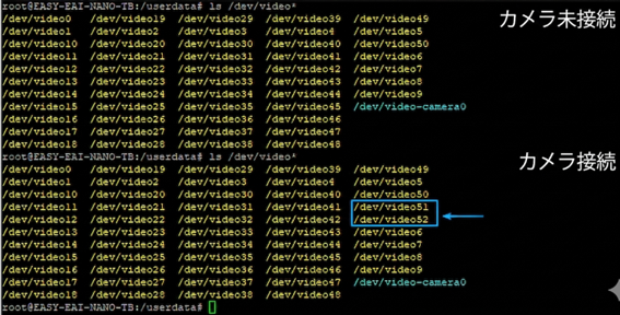
Searching for Available Device Nodes
However, the most accurate method is to check the description information of these video nodes. In the Linux v4l2 framework, the description information for all these nodes is collected under the /sys/class/video4linux/ directory.
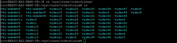
Searching for Available Device Nodes
Enter any description directory, for example video22, and use the cat command to check the contents of the name file.

Searching for Available Device Nodes
cat /sys/class/video4linux/video22/name
Searching for Available Device Nodes
Therefore, use the following command to scan and filter all video nodes.
grep -i "usb" /sys/class/video4linux/video\*/name
Searching for Available Device Nodes
2.2 Quick Start
2.2.1 Preparing the Development Environment
On the Ubuntu system on the PC side, run the run script to enter the EASY-EAI compilation environment. The details are as follows.
cd ~/develop_environment./run.sh 22042.2.2 Downloading Source Code and Compiling the Sample
First, run the following command in the background terminal of the virtual machine to create a management directory for the peripheral sample source code:
cd /optmkdir -p EASY-EAI-Nano-TB/demoNext, download the sample program:
Then copy the downloaded sample to the file system of the virtual machine.
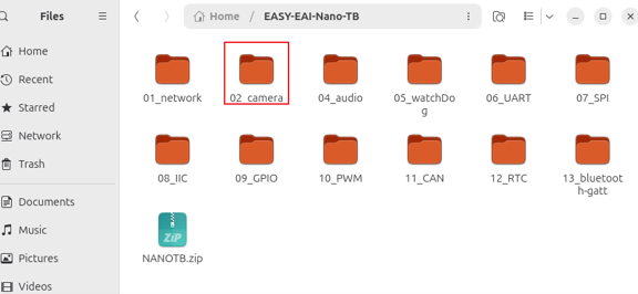
Downloading Source Code and Compiling the Sample
Finally, go to the corresponding sample directory and execute the compilation operation. The specific commands are as follows:
cd EASY-EAI-Nano-TB/demo/02_camera./build.sh💡 Note: Because the dependent libraries are located on the board, the /mnt mount must be maintained during cross-compilation.
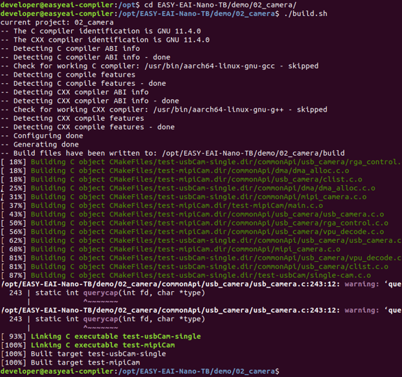
2.2.3 Running the Sample
Access the board backend through serial-port debugging or SSH, and go to the directory where the sample is located:
cd /userdata
Running the Sample
The command for running the sample is as follows (51 means /dev/video51 being used):
./test-usbCam-single 512.2.4 Execution Result

Execution Result
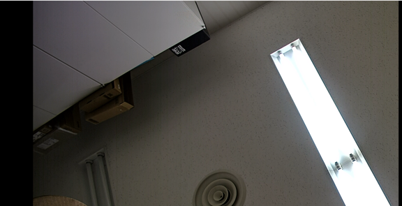
After the sample finishes running, an image file named photo is generated in the /tmp directory. Return to the virtual machine, open a new terminal window, and use the scp command to copy the image to the local machine.

Execution Result
Then use the mplayer command to play back (display) the captured photo file.
mplayer -demuxer rawvideo -rawvideo w=1280:h=720:format=bgr24 photo -loop 0Because the default resolution of the sample is 1280x720, set the w and h parameters to 1280 and 720 respectively. If the image is not displayed correctly, the resolution may not match your camera, so you need to adjust the resolution in usbcamera_init(), for example to 640x480.
Execution Result
2.3. USB Camera API Test Case
The sample code path is 02_camera/test-usbCam/single-cam.c.
Execution Result
2.3.1 Source Code Description
int main(int argc, char **argv){    if(1 == argc){        printf("\nerr: Missing parameter!\n");        printf("================= [usage] ==================\n");        printf("example:\n");        printf("\t%s <51/52>\n", argv[0]);        printf("--------------------------------------------\n");        return 0;    }    int cameraIndex = atoi(argv[1]);
    char *pbuf = NULL;    int ret = 0;    int skip = 0;    FILE *fp = NULL;
    ret = usbcamera_init(cameraIndex, CAMERA_WIDTH, CAMERA_HEIGHT, 0);    if (ret) {        printf("error: %s, %d\n", __func__, __LINE__);        goto exit3;    }
    pbuf = (char *)malloc(IMAGE_SIZE);    if (!pbuf) {        printf("error: %s, %d\n", __func__, __LINE__);        ret = -1;        goto exit2;    }
    // Skip the first 10 frames to stabilize exposure and other settings    skip = 10;    while(skip--) {        ret = usbcamera_getframe(cameraIndex, pbuf);        if (ret) {            printf("error: %s, %d\n", __func__, __LINE__);            goto exit1;        }    }
    /* tips: In the Ubuntu environment, you can use mplayer to display the captured image    *  mplayer -demuxer rawvideo -rawvideo w=1280:h=720:format=bgr24 photo -loop 0    */    fp = fopen("/tmp/photo", "w");    if (!fp) {        printf("error: %s, %d\n", __func__, __LINE__);        ret = -1;        goto exit2;    }    fwrite(pbuf, 1, IMAGE_SIZE, fp);    fclose(fp);
exit1:    free(pbuf);    pbuf = NULL;exit2:    usbcamera_exit(cameraIndex);exit3:    return ret;}
In the code, usbcamera_init(), usbcamera_getframe(), and usbcamera_exit() are wrapper functions that simplify calls to the v4l2 interface. The specific implementation is described in 02_camera/commonApi/usb_camera/usb_camera.c.
3.MIPI-DSI
3.1. Overview of MIPI-DSI
MIPI (Mobile Industry Processor Interface) is an interface defined by an alliance established in 2003 by companies such as ARM, Nokia, ST, and TI. Its purpose is to standardize internal interfaces in mobile devices such as smartphones, including camera interfaces, display interfaces, and RF/baseband interfaces, thereby reducing the complexity of mobile-device design and improving design flexibility. Under the MIPI Alliance, there are many working groups that define standards for their corresponding devices. These include more than ten groups such as the Camera Working Group, Display Working Group, and High-Speed Multipoint Link Working Group. The MIPI DSI interface is the DSI (Display Serial Interface) interface standard defined by the Display Working Group of the MIPI Alliance.
3.1.1 EASY EAI Nano-TB DSI
The DSI interface does not support hot swapping. It also has certain power-supply requirements. Therefore, before using the DSI interface, first make sure that the input power supply is DC12V-3A. Otherwise, insufficient power may prevent the DSI screen from being driven. A typical symptom is repeated reboots during the U-Boot stage.
3.1.2 Connection Cable Description
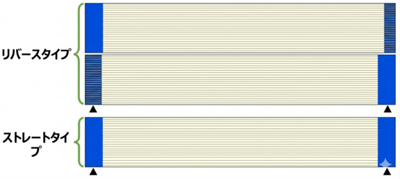
-
Reverse cable: The blue plastic identification marks at the two ends are not on the same side.
-
Straight cable: The blue plastic identification marks at the two ends are on the same side.
Connection Cable Description
3.1.3 Hardware Interface Description
-
The MIPI interface does not support hot swapping. Be sure to perform wiring only when the power is turned off.
-
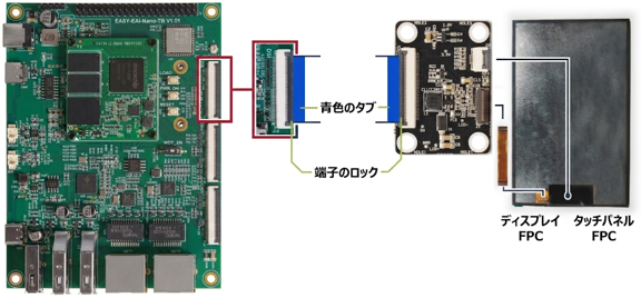
Use a straight cable to connect the screen to the MIPI-DSI0 interface. (Note: If the wrong cable type is used, the camera or core board may be burned out. Please be careful when wiring.)
-
Make sure the connector lock and the blue plastic identification mark on the FPC cable are on the same side. See the figure below for details.
Hardware Interface Description
3.2. Driver Support Description
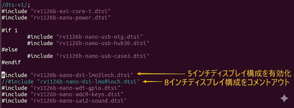
In the default firmware, MIPI-DSI supports an 8-inch MIPI display. If the system needs to support displays of other sizes or models, the kernel image must be modified and replaced. This includes the following steps.
3.2.1 Upgrade to the Latest Firmware
3.2.2 Download the Ubuntu System SDK Source Code
For downloading the ubuntu_sdk source code, mainly the kernel source code, refer to “Embedded Low-Level Development / Ubuntu System SDK / Obtaining the Source Code”.
3.2.3 Modify the Kernel Device Tree
According to the instructions in “Embedded Low-Level Development / Ubuntu System SDK / kernel”, users can build and manage the kernel source-code development repository as needed.
Then, according to the figure below, modify the device tree file in the kernel source-code development repository:
Modify the Kernel Device Tree
- EASY-EAI-Nano-TB device tree entry point: arch/arm64/boot/dts/rockchip/rv1126b-nano.dts
After compilation, a new boot.img is generated.
3.2.4 Update the Kernel Image
Copy the boot.img generated in the previous step to the firmware rockdev directory to replace the original boot.img, and then flash boot.img to the development board.
3.3.1 Default Display Result
After confirming that the wiring is correct, power on the device. A boot logo like the one shown below will be displayed.

Default Display Result
3.3.2 Changing the Boot Logo
To change the boot logo, refer to the “Application Notes / How to Change the Boot Logo” document.
3.3.3 Installing the Desktop System
After powering on the device, the screen will always display the logo. If you need to install the desktop system, refer to “Application Notes / Desktop System Installation”.
3.3.4 UI Application Development
If users need to develop UI applications, refer to “EASY-EAI-Solution (Development Examples) / QT GUI Sample”.
4. Audio Output
4.1. Overview of Sound Card Resources
The EASY-EAI-Nano-TB has only one sound card output from the RV1126B main controller.
You can access the terminal of the development board through serial-port debugging or SSH debugging. Run the aplay command to view detailed information about the sound card. The details are as follows.
aplay -l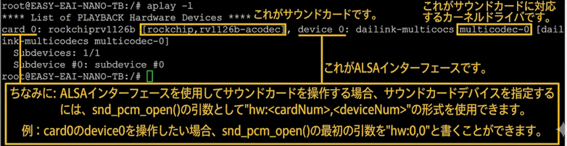
Overview of Sound Card Resources
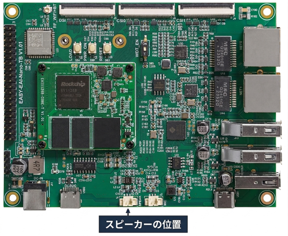
4.1.1 Hardware Interface
The location of the hardware interface is as follows.
Hardware Interface
4.2. Sound Card Control
In Linux systems, the ALSA framework (aplay, arecord, and amixer) is usually used when calling the sound card from the application layer. This document describes only the parts related to this development board platform. For more details about using ALSA, refer to “Overview of ALSA Usage” in the developer community.
4.2.1 Audio Playback
Use the aplay command for audio playback.
aplay -D plughw:0,0 test.wav \## Audio is output from Card04.2.2 Volume Adjustment
The range of the output-volume value of Card0 is 0 to 510.
amixer -c 0 cset name='DAC Digital Volume' 0,0 ## Set the output-volume value of Card0 to 0amixer -c 0 cset name='DAC Digital Volume' 192,192 ## Set the output-volume value of Card0 to 192amixer -c 0 cset name='DAC Digital Volume' 255,255 ## Set the output-volume value of Card0 to 255💡 Note: The value here is a variable that is positively correlated with gain, but it is neither the gain itself nor a volume percentage. In addition, the volume change caused by adjusting it is not linear.
-
0〜255: This is the digital gain section. When set to 255, it produces the maximum volume without distortion.
-
256〜510: This is the analog gain section. When the value exceeds 255, distortion occurs in the audio output.
4.3. Notes on Using the Sound Card
The I2S/SAI controller used at the hardware level does not itself support usage scenarios such as mono or mixing. However, users can perform data conversion through alsa-plug. The specific operation is to edit the ~/.asoundrc file.
4.3.1 Channel Conversion
Because the I2S/SAI controller does not support mono, a “2x playback speed” phenomenon occurs when users try to play mono audio files. Therefore, users need to edit the ~/.asoundrc file to perform channel conversion. Add the following content to the file:
pcm.!default{    type asym    playback.pcm "playbackmono"    capture.pcm "hw:0,0"}
pcm.playbackmono {    type route    slave.pcm "hw:0,0"  # Output to sound card device hw:0,0    slave.channels 2    ttable {            # Channel route settings        0.0 0.5        0.1 0.5        1.0 0.5        1.1 0.5    }}
Then, when playing audio files, change the command as follows:
aplay -D default test_mono.wavor
aplay -D playbackmono test_mono.wav5. Audio Input
5.1 Introduction to Sound Card Resources
The EASY-EAI-Nano-TB is equipped with only one sound card output from the RV1126B main controller.
You can access the terminal of the development board through serial-port debugging or SSH debugging. Run the aplay command to view detailed information about the sound card. The result is as follows.
arecord -l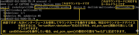
Introduction to Sound Card Resources
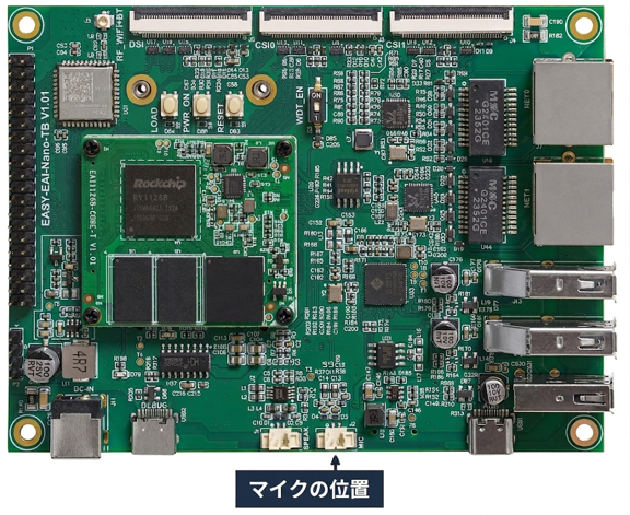
5.1.1 Hardware Interface
The location of the hardware interface is as follows.
Hardware Interface
5.2 Sound Card Control
In Linux systems, the ALSA framework (aplay, arecord, and amixer) is usually used when calling the sound card from the application layer. This article describes only the parts related to this development board platform. For more details about using ALSA, refer to “Overview of ALSA Usage” in the developer community.
5.2.1 Audio Recording
Use the arecord command for audio recording.
arecord -D plughw:0,0 -c 2 -r 44100 -f S16_LE 1234567.wavPress Ctrl+C to stop recording.
💡 Note: When recording mono (-c 1) audio, -f supports only two sampling bit depths: S16_LE and S24_LE.
5.2.2 Recording Volume Adjustment
The range of the recording-volume value of Card0 is 0 to 31.
amixer -c 0 cset name='ACodec_LP PGA Gain Volume' 0 ## Set the output-volume value of Card0 to 0amixer -c 0 cset name='ACodec_LP PGA Gain Volume' 16 ## Set the output-volume value of Card0 to 16amixer -c 0 cset name='ACodec_LP PGA Gain Volume' 31 ## Set the output-volume value of Card0 to 31💡 Note: The value here is a variable that is positively correlated with gain, but it is neither the gain itself nor a volume percentage. In addition, the volume change caused by adjusting it is nonlinear.
5.2.3 Recording Command Details
Record in CD format (press Ctrl+C to stop recording):
arecord -D hw:0,0 -f cd 1234567.wavSpecifying the CD recording format is equivalent to fixing the channels (stereo/2 channels), sampling rate (44100 Hz), and sampling bit depth (S16_LE).
Specify the recording duration:
arecord -D hw:0,0 -f cd -d 10 1234567.wav-d 10: specifies the recording duration as 10 seconds, after which recording stops automatically. For more ways to use arecord, refer to:
arecord -h |