
Serial Bus and Control Interfaces
1.UART
1.1. UART Overview
1.1.1 Serial Port Resource Introduction
EASY EAI The serial port resources of the Nano-TB development board are divided into two categories: [unavailable serial ports] occupied by specific functions, and [available serial ports] that users can use freely.
The distribution of [serial ports that cannot be used directly] is as follows.
| Serial port number | Device node | Description |
|---|---|---|
| Port 0 | /dev/ttyFIQ0 | Occupied for debugging. It cannot be used as a normal port. |
| Port 1 | None | The related pins are multiplexed to other functions. |
| Port 3–5 | None | The related pins are multiplexed to other functions. |
The hardware layout is shown in the figure.
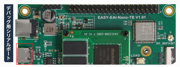
Serial Port Resource Introduction
The distribution of [available serial ports] is as follows.
| Serial port number | Device node | Description |
|---|---|---|
| Port 2 | /dev/ttyS2 | TTL level |
| Port 6 | /dev/ttyS6 | TTL level |
| Port 7 | /dev/ttyS7 | TTL level |
The hardware layout is shown in the figure.
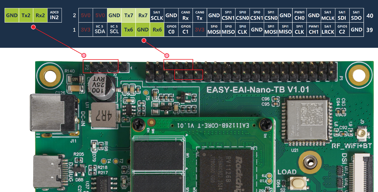
Serial Port Resource Introduction
1.1.2 Hardware Wiring
General wiring (communication between devices):
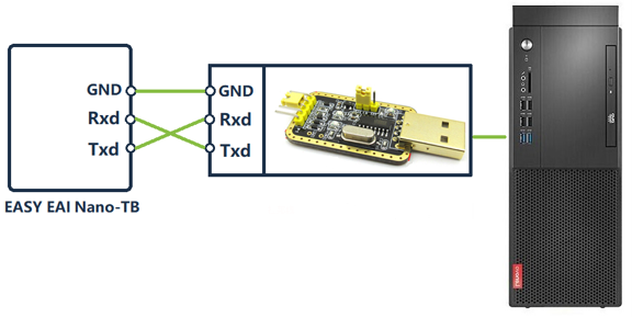
Hardware Wiring
- Test wiring for this sample: Use a jumper cap to short the Rxd and Txd pins and perform a loopback test (self-send/self-receive).
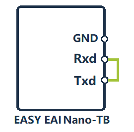
Hardware Wiring
1.2. Quick Start
1.2.1 Preparing the Development Environment
If you are reading this document for the first time, read “Getting Started/Preparing the Development Environment/Preparing and Updating the Easy-EAI Compilation Environment” and follow the related steps to set up the compilation environment.
On the PC-side Ubuntu system, run the run script to enter the EASY-EAI compilation environment. The details are as follows.
cd ~/develop_environment./run.sh 22041.2.2 Downloading the Source Code and Compiling the Sample
First, run the following commands in the background terminal of the virtual machine to create the management directory for the peripheral sample source code:
cd /optmkdir -p EASY-EAI-Nano-TB/demoDownload the sample program:
For example, download the sample program to “PC\D:” (there is no specific requirement; any location chosen by the user is acceptable).
Then copy the downloaded sample to the file system of the virtual machine. Refer to the figure below for the procedure.
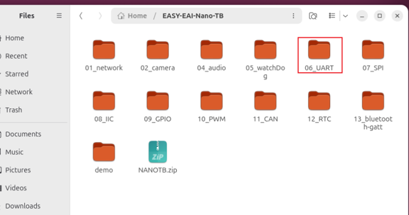
Downloading the Source Code and Compiling the Sample
Finally, go to the corresponding sample directory and run the compilation operation. The specific commands are as follows:
cd EASY-EAI-Nano-TB/demo/06_UART./build.sh💡 Note : Because the dependent libraries are located on the board, the /mnt mount must be kept during cross-compilation.
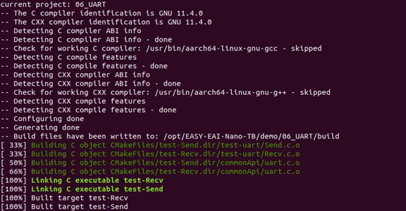
After compilation succeeds, two executable programs are generated in the Release directory and automatically placed in the /userdata/ directory of the development board: test-Send for the sender demo and test-Recv for the receiver demo.
1.2.3 Running the Sample
Access the board background through serial-port debugging or SSH, and go to the directory where the sample is located:
cd /userdata
Running the Sample
First, run the following command to run the [receiver] demo [in the background]:
sudo ./test-Recv /dev/ttyS2 &The execution result is as follows. At this point, the receiver waits for data from the sender.

Running the Sample
Next, run the following command to start the [sender] demo:
sudo ./test-Send /dev/ttyS2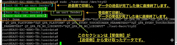
Running the Sample
1.3. C Language Usage Example
This is a C-language usage example for the serial port. The receiver code path is 06_UART/test-uart/Recv.c. Use it as a coding reference. The following code shows the operation flow of the serial-port receiver:
int main(int argc, char **argv){    if(2 != argc){        printf("Usage:\n");        printf("    sudo %s %s\n", argv[0], "/dev/ttyS<2/6/7>");        return -1;    }
    int fd = UART_Open(argv[1]);    if(fd < 0){        printf("\033[33m[Open ERROR!]%s\n", DEBUG_COLOR_TAIL);        return -1;    }
    if(false == UART_Set(fd, 115200, 0, 8, 1, 'N')){        printf("\033[33m[Init ERROR!]%s\n", DEBUG_COLOR_TAIL);        return -1;    }
    const char *strReceiver = "I am uart Receiver";    printf("\033[36m[Init OK \"%s\"]%s\n", strReceiver, DEBUG_COLOR_TAIL);
    char recvBuf[128]={0};    while(1){        if(UART_Recv(fd, recvBuf, sizeof(recvBuf)) <= 0){            continue;        }else{            printf("\033[36m[Recv Msg from Sender]:%s",   DEBUG_COLOR_TAIL);            printf("    %s\n", recvBuf);            break;        }    }    UART_Close(fd);
    printf("\033[42m[Recv date OK. BYE BYE!]%s\n", DEBUG_COLOR_TAIL);
    return 0;}
The sender code path is 06_UART/test-uart/Send.c. Use it as a coding reference. The following code shows the operation flow of the serial-port sender:
int main(int argc, char **argv){    if(2 != argc){        printf("Usage:\n");        printf("    sudo %s %s\n", argv[0], "/dev/ttyS<2/6/7>");        return -1;    }
    int fd = UART_Open(argv[1]);    if(fd < 0){        printf("\033[33m[Open ERROR!]%s\n", DEBUG_COLOR_TAIL);        return -1;    }
    if(false == UART_Set(fd, 115200, 0, 8, 1, 'N')){        printf("\033[33m[Init ERROR!]%s\n", DEBUG_COLOR_TAIL);        return -1;    }
    char *strSender = "I am uart Sender";    printf("\033[36m[Init OK \"%s\"]%s\n", strSender, DEBUG_COLOR_TAIL);
    int len = UART_Send(fd, strSender, strlen(strSender));    if(len <= 0){        printf("\033[41m[Send data ERROR!]%s\n", DEBUG_COLOR_TAIL);        return -1;    }    UART_Close(fd);
    printf("\033[42m[Send date OK. BYE BYE!]%s\n", DEBUG_COLOR_TAIL);
    return 0;}
In the code, UART_Open(), UART_Set(), UART_Send(), UART_Recv() are wrapper functions that encapsulate system calls for easier use. The specific implementation is described in 06_UART/commonApi/uart.c.
2.SPI
2.1. SPI Overview
SPI stands for Serial Peripheral Interface. It is a synchronous serial interface technology developed by Motorola and functions as a high-speed, full-duplex, synchronous communication bus. In user-space applications, you do not need to worry about the detailed SPI protocol specifications. By using the SPI peripheral operation interface functions provided by the driver layer, you can easily operate SPI peripherals just like other common device files in Linux.
The SPI interface layout of the EASY EAI Nano-TB is shown in the figure.
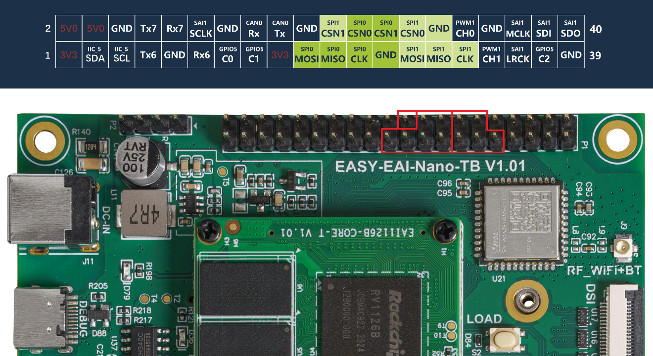
SPI Overview
2.1.1 Explanation of SPI Parameter Settings
-
Device file format: /dev/spidev(bus.select)
-
bus: Represents the SPI bus number (that is, one set of SCLK, MOSI, and MISO).
-
select: Represents the SPI device number. On the same bus, devices are distinguished by different chip-select signals (CSN0, CSN1, etc.).
Taking the default SPI resources of Orin-Nano as an example: when the SPI function is enabled, the following four device nodes appear (that is, two buses and four devices exist).
-
/dev/spidev0.0
-
/dev/spidev0.1
-
/dev/spidev1.0
-
/dev/spidev1.1
SPI communication has four different modes. The slave device mode is fixed at the factory and cannot be changed. However, both communicating devices must operate in the same mode, so the SPI mode on the master side must be configured, and the master communication mode is controlled through CPOL (clock polarity) and CPHA (clock phase).
| Mode | CPOL | CPHA |
|---|---|---|
| Mode 0 | 0 | 0 |
| Mode 1 | 0 | 1 |
| Mode 2 | 1 | 0 |
| Mode 3 | 1 | 1 |
-
Clock polarity (CPOL) is used to set the active level of SCLK.
-
Clock phase (CPHA) is used to set on which edge data sampling occurs.
-
CPOL=0 indicates that the idle state is when SCLK=0, and it is active when SCLK is High.
-
CPOL=1 indicates that the idle state is when SCLK=1, and it is active when SCLK is Low.
-
CPHA=0 indicates that data is sampled on the first edge and transmitted on the second edge.
-
CPHA=1 indicates that data is sampled on the second edge and transmitted on the first edge.
[*] Between the SPI master module and the communicating peripheral, the clock phase and polarity of both sides must match.
Other parameters:
-
speed: communication bit rate
-
delay: communication delay-time setting
-
bits: number of bits occupied by communication
2.1.2 Hardware Connection
In this sample, the RC522 RFID card-reader module is used for an auxiliary demonstration.
The wiring schematic between the RC522 module and the EASY EAI Nano-TB is as follows.
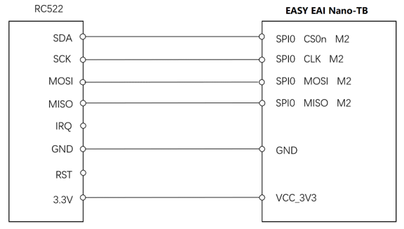
Hardware Connection
2.2. Quick Start
2.2.1 Preparing the Development Environment
If you are reading this document for the first time, read “Getting Started/Preparing the Development Environment/Preparing and Updating the Easy-EAI Compilation Environment” and follow the related steps to set up the compilation environment.
On the PC-side Ubuntu system, run the run script to enter the EASY-EAI compilation environment. The details are as follows.
cd ~/develop_environment./run.sh 22042.2.2 Downloading the Source Code and Compiling the Sample
First, run the following commands in the background terminal of the virtual machine to create the management directory for the peripheral sample source code:
cd /optmkdir -p EASY-EAI-Nano-TB/demoDownload the sample program:
For example, download the sample program to “PC\D:” (there is no specific requirement; any location chosen by the user is acceptable).
Then copy the downloaded sample to the file system of the virtual machine. Refer to the figure below for the procedure.
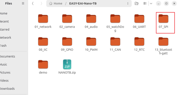
Downloading the Source Code and Compiling the Sample
Finally, go to the corresponding sample directory and run the compilation operation. The specific commands are as follows:
cd EASY-EAI-Nano-TB/demo/07_SPI./build.sh💡 Note : Because the dependent libraries are located on the board, the /mnt mount must be kept during cross-compilation.
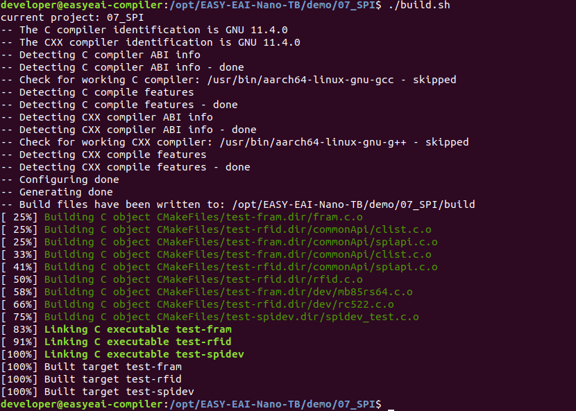
After compilation succeeds, three sample programs, test-rfid, test-fram, and test-spidev, are generated based on the source code and are automatically placed in the /userdata/ directory of the development board.
The auxiliary sample used in this document is test-rfid. The other samples are used in other application scenarios, and the code here is for reference.
2.2.3 Running the Sample
Access the board background through serial-port debugging or SSH, and go to the directory where the sample is located:
cd /userdata
Running the Sample
Run the following command to start the sample:
sudo ./test-rfid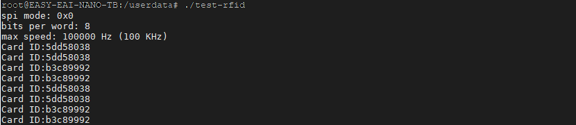
Running the Sample
The execution result is shown in the figure (refer to the figure in the original document).
For detailed API descriptions and API calls (the source code of this sample), refer to the following explanation.
2.3. RFID ID Reading Sample
The source code of the RFID sample is located at the following path:
-
07_SPI/rfid.c
-
07_SPI/dev/rc522.c
-
07_SPI/include/rc522.h
The implementation and explanation use the RC522 chip. The operation flow is as follows.
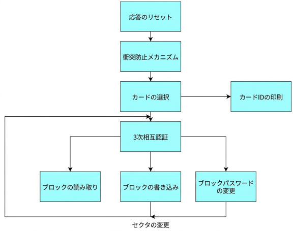
RFID ID Reading Sample
The reference sample code is as follows.
static unsigned char flag = 0; static unsigned char bits = 8; static unsigned int speed = 100000; static uint16_t delay = 0; unsigned char card_rev_buf[16] = 0;
/* * Sector password: A, number of sectors: 16 * Password byte count per sector: 16 Byte */unsigned char sector_key_a[16][16];unsigned char data_buf[16] = {0x01, 0x02, 0x03, 0x04, 0x05, 0x06, 0x07, 0x08, 0x09, 0x0A, 0x0B, 0x0C, 0x0D, 0x0E, 0x0F, 0x10};
int main (int argc, char **argv) {    memset(data_buf, 0x00, sizeof data_buf);    int status = MI_ERR;    int numAtempt = 1;    int fd = spi_init(dev_spi_bus, dev_spi_select, mode, bits, speed, delay);    rfid_init(dev_spi_bus, dev_spi_select, fd);    flag = MI_GET_ID;
    while(1)    {        while(rfid_request(PICC_REQIDL, &card_rev_buf[0]) != MI_OK && numAtempt-- >= 0) {            usleep(500);        }        if(rfid_anticoll(&card_rev_buf[2]) == MI_OK) {            status = rfid_select(&card_rev_buf[2]);            if(status != MI_ERR) {                if(flag == MI_GET_ID) {                    printf("Card ID:%02x%02x%02x%02x\n", card_rev_buf[2], card_rev_buf[3],card_rev_buf[4], card_rev_buf[5]);                } else if (flag == MI_READ) {                    memset(sector_key_a, 0xff, 256);                    memset(data_buf, 0x00, sizeof data_buf);                    status = rfid_auth_state(PICC_AUTHENT1A, addr, sector_key_a[addr/4], &card_rev_buf[2]);                    if(status == MI_OK) {                        status = rfid_read(addr, data_buf);                        if(status == MI_OK) {                            print_buff(data_buf, 16);                        }                    } else {                        printf("Error reading");                        close(fd);                        exit(1);                    }                } else if (flag == MI_WRITE) {                    memset(sector_key_a, 0xff, 256);                    if(addr == 0 || addr % 4 == 3) {                        close(fd);                        exit(1);                    }                    status = rfid_auth_state(PICC_AUTHENT1A, addr, sector_key_a[addr/4], &card_rev_buf[2]);                    if(status == MI_OK) {                        status = rfid_write(addr, data_buf);                        if(status != MI_OK) {                            printf("rfid write failure!\n");                            close(fd);                            exit(1);                        }                    } else {                        printf("Error writing");                        close(fd);                        exit(1);                    }                } else {                    printf("Not implemented\n");                }                status = rfid_halt();                if(status != MI_OK)  {                    //printf ("rfid halt failure! [ERROR %d]\n", status);                }            } else {                // printf("None\n");            }        } else {            // printf("None\n");        }    }    spi_exit(dev_spi_bus , dev_spi_select);    return 0;} /* ----- End of main() ----- */
In addition, the communication source code for FRAM (ferroelectric memory) using the SPI interface is located at the following path:
-
07_SPI/fram.c
-
07_SPI/mb85rs64.c
-
07_SPI/mb85rs64.h
The read/write communication source code for the SPI interface is located at the following path:
- 07_SPI/spidev_test.c
2.4. Notes
The RC522 is mainly used to assist with explaining the SPI API usage method. For the documentation and detailed usage of this module, refer to the following site:
www.xxx.com(※official module URL)
3.I2C
3.1. I2C Overview
IIC (or I2C) is a serial communication bus that uses a multi-master, multi-slave architecture. It was originally designed to connect low-speed peripherals in motherboards, embedded systems, or mobile phones. It is mainly used when the data volume is small, has a short transmission distance, and allows only one master at any given time. In Linux embedded application development scenarios, you do not need to worry about the detailed IIC protocol specifications. By using the IIC peripheral operation interface functions provided by the driver layer, you can easily operate IIC peripherals just like other common device files in Linux.
3.1.1 Introduction to I2C Resources on the Development Board
The EASY EAI Nano-TB development board exposes one IIC resource (IIC_5) as a reserved interface for users to call custom functions. The exact location is shown in the figure below.
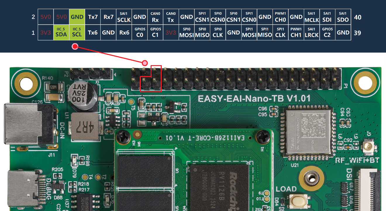
Introduction to I2C Resources on the Development Board
3.1.2 Hardware Wiring Diagram
In this sample, the ADS1115 voltage detection module is used for an auxiliary demonstration. This module converts the detected voltage (analog signal) into a digital signal, stores it in registers, and provides voltage information externally through IIC communication.
The wiring schematic between the ADS1115 module and the EASY EAI Nano-TB is as follows.
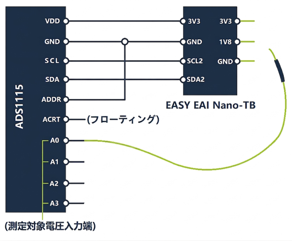
Hardware Wiring Diagram
3.2. Quick Start
3.2.1 Preparing the Development Environment
On the PC-side Ubuntu system, run the run script to enter the EASY-EAI compilation environment. The details are as follows.
cd ~/develop_environment./run.sh 22043.2.2 Downloading the Source Code and Compiling the Sample
First, run the following commands in the background terminal of the virtual machine to create the management directory for the peripheral sample source code:
cd /optmkdir -p EASY-EAI-Nano-TB/demoDownload the sample program:
For example, download the sample program to “PC\D:” (there is no specific requirement; any location chosen by the user is acceptable).
Finally, go to the corresponding sample directory and run the compilation operation. The specific commands are as follows:
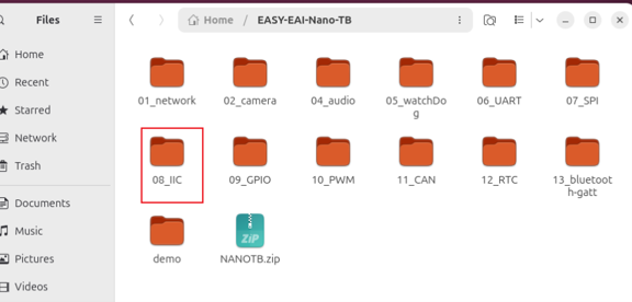
Downloading the Source Code and Compiling the Sample
cd EASY-EAI-Nano-TB/demo/08_IIC./build.sh💡 Note :Because the dependent libraries are located on the board, the /mnt mount must be kept during cross-compilation.
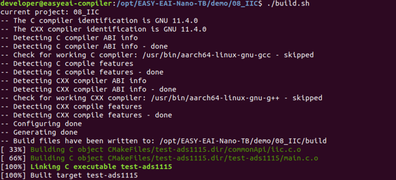
Downloading the Source Code and Compiling the Sample
After compilation succeeds, an executable program named test-ads1115 is generated and automatically placed in the /userdata/ directory of the development board.
3.2.3 Running the Sample
Access the board background through serial-port debugging or SSH, and go to the directory where the sample is located:
cd /userdata
Running the Sample
Run the following command to start the sample:
sudo ./test-ads1115The execution result is as follows. When using a probe to touch the three terminals 3V3, 1V8, and GND respectively, the corresponding voltage values are measured and displayed in the terminal.
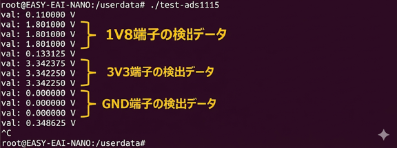
Running the Sample
3.3. C Language Usage Example
This is a C-language usage example for ADS1115. The code path is 08_IIC/test-ads1115/main.c Use it as a coding reference. The following code shows the ADS1115 operation flow:
int32_t ads1115_config_register(uint32_t fd, uint8_t configH, uint8_t configL){    uint8_t reg_data[3] = {ADS1015_REG_POINTER_CONFIG, configH, configL};    return iic_write(fd, ADS1115_ADDRESS, reg_data, sizeof(reg_data));}
int16_t ads1115_read_data(uint32_t fd){    bool ret = false;    /* Read data */    uint8_t tx_data[1] = {ADS1015_REG_POINTER_CONVERT};    if(iic_write(fd, ADS1115_ADDRESS, tx_data, sizeof(tx_data)) < sizeof(tx_data)){        printf("iic write faild !\n");        return -1;    }
    uint8_t rx_data[3]={0};    if(iic_read(fd, ADS1115_ADDRESS, rx_data, 2) < 0){        printf("iic read faild !\n");        return -1;    }
    int16_t data = rx_data[0]*256+rx_data[1];    return data;}
double ads1115_get_voltage_val(uint32_t fd, uint8_t configH, uint8_t configL){    /* Configure the register */    if(ads1115_config_register(fd, configH, configL) < 0){        printf("ads1115 config register faild\n");        return 0.0;    }    usleep(100 * 1000);
    int16_t ad_val = ads1115_read_data(fd);    if((0x7FFF == ad_val)|(0X8000 == ad_val)) { // Check whether the range is exceeded        ad_val = 0;        printf("ads1115 over PGA\r\n");    }
    double val = 0.0;    switch((0x0E&configH)>>1) // Resolution corresponding to the range    {        case(0x00):            val = (double)ad_val*187.5/1000000.0; break;        case(0x01):            val = (double)ad_val*125/1000000.0; break;        case(0x02):            val = (double)ad_val*62.5/1000000.0; break;        case(0x03):            val = (double)ad_val*31.25/1000000.0; break;        case(0x04):            val = (double)ad_val*15.625/1000000.0; break;        case(0x05):            val = (double)ad_val*7.8125/1000000.0; break;        default:            val = 0.0; break;    }
    return val;}
int main(int argc, char const *argv[]){    bool ret = false;    double val;    int fd = iic_init("/dev/i2c-2");    if(fd < 0){        printf("iic init faild \n");        return -1;    }
    if(0 != iic_set_addr_len(fd, 7)){        return -1;    }
    if(0 != iic_set_addr(fd, ADS1115_ADDRESS)){        return -1;    }
    while (1) {        val = ads1115_get_voltage_val(fd, CONFIG_REG_H, CONFIG_REG_L);        printf("val: %f V\r\n",val);        sleep(2);    }
    iic_release(fd);    return 0;}
In the code, iic_init(), iic_set_addr_len(), iic_set_addr(), iic_read(), iic_write(), and iic_release() are wrapper functions that encapsulate system calls for easier use. The specific implementation is described in 08_IIC/commonApi/iic.c.
In addition to requiring an interface for operating IIC hardware resources, you must clearly understand how to operate the registers of IIC slave devices on the IIC bus. For example, for the ADS1115 voltage detection chip, all register-related operation definitions are implemented in 08_IIC/test-ads1115/ads1115.h.
4.GPIO
4.1. GPIO Overview
4.1.1 Hardware Wiring Schematic
💡 Note : GPIO supports hot swapping, but if plugging and unplugging is performed when the baseboard is not equipped with a protective case, it is easy to touch components on the baseboard, and nearby metal parts may cause a short circuit. Therefore, it is recommended to plug and unplug peripherals only after the power is completely turned off.
The GPIO input/output voltage is 3.3 V. Pay attention to level (voltage potential) matching. Otherwise, the chip pins or connected devices may be damaged.
4.1.2 Introduction to GPIO Hardware Resource Distribution
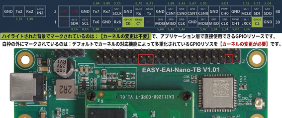
Introduction to GPIO Hardware Resource Distribution
-
gpiod library: You need to use the [Chip object name] and [Line offset] in the table above.
-
sysfs access method: You need to use the [GPIO system node path] in the table above.
4.1.3 gpiod Overview
Support for libgpiod was added starting from Linux 4.8, and the traditional sysfs-based access method is gradually being deprecated. Therefore, the demos in this document mainly use the gpiod method to control GPIO. The gpiod library operates chip objects and line objects to control GPIO pin output levels or read GPIO pin levels.
-
Chip object name: gpiod_chip_open_by_name is used as an argument when calling it to obtain a chip object.
-
Line offset: gpiod_chip_get_line is used as an argument when calling it to obtain a line object.
Taking GPIO5_C0 as an example, the relationship among [pin name], [Chip object name], and [Line offset] is as shown in the following formula.
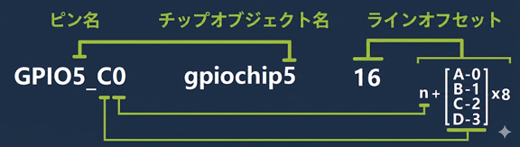
gpiod Overview
3.1.4 sysfs Access Method Overview
The GPIO control method through sysfs is mainly based on GPIO control interface files provided by the kernel. That is, the corresponding GPIO interface is controlled by reading and writing files under the /sys/class/gpio directory.
-
Pin number (pin): In the sysfs access method, all operations are based on the pin number.
-
GPIO system node path: This is the node path corresponding to the specific GPIO pin.
The relationship between [pin name] and [GPIO system node path] is as shown in the following formula.
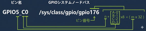
sysfs Access Method Overview
Request to export the pin: Before using a pin, you need to manually request the GPIO manager to export the corresponding pin resource.
echo 176 \> /sys/class/gpio/export \## gpio_request request export of the corresponding GPIOSet the operating mode of the corresponding pin (input or output).
echo in > /sys/class/gpio/gpio176/direction ## gpio_direction_output set the corresponding GPIO to input direction## orecho out > /sys/class/gpio/gpio176/direction ## gpio_direction_output set the corresponding GPIO to output directionPerform the corresponding control (level writing or reading) according to the operating mode of the pin.
cat /sys/class/gpio/gpio176/value ## gpio_get_value get the current status value of the GPIO## orecho 0 > /sys/class/gpio/gpio176/value ## gpio_set_value set output to Low level (low potential)echo 1 > /sys/class/gpio/gpio176/value ## gpio_set_value set output to High level (high potential)Request to release the pin: After using the pin, you need to manually request the GPIO manager to release the corresponding pin resource.
echo 176 \> /sys/class/gpio/unexport \## gpio_free release the requested GPIO4.2. Quick Start
4.2.1 Preparing the Development Environment
On the PC-side Ubuntu system, run the run script to enter the EASY-EAI compilation environment. The details are as follows.
cd ~/develop_environment./run.sh 22044.2.2 Downloading the Source Code and Compiling the Sample
First, run the following commands in the background terminal of the virtual machine to create the management directory for the peripheral sample source code:
cd /optmkdir -p EASY-EAI-Nano-TB/demoDownload the sample program:
For example, download the sample program to “PC\D:” (there is no specific requirement; any location chosen by the user is acceptable).
Then copy the downloaded sample to the file system of the virtual machine. Refer to the figure below for the procedure.
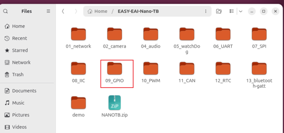
Downloading the Source Code and Compiling the Sample
Finally, go to the corresponding sample directory and run the compilation operation. The specific commands are as follows:
cd EASY-EAI-Nano-TB/demo/09_GPIO./build.sh💡 Note : Because the dependent libraries are located on the board, the /mnt mount must be kept during cross-compilation.
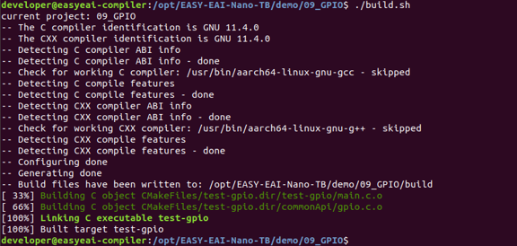
Downloading the Source Code and Compiling the Sample
After compilation succeeds, the related demos are generated in the Release directory and automatically placed in the /userdata/ directory of the development board.
4.2.3 Running the Sample
Access the board background through serial-port debugging or SSH, and go to the directory where the sample is located:
cd /userdata
Running the Sample
Run the following command to start the sample:
sudo ./test-gpioThe execution result is as follows.

Running the Sample
Furthermore, if [GPIO5_C0] and [GPIO5_C1] are shorted with a wire, the [High level] output by [GPIO5_C0] can be read from the [GPIO5_C1] pin. The details are as follows.

Running the Sample
4.3. C Language Usage Example
This is a C-language usage example for GPIO. The code path is 09_GPIO/test-gpio/main.c Use it as a coding reference. The following code shows the GPIO operation flow:
#define ARRAY_SIZE(x) (sizeof(x) / sizeof((x)[0]))
static const GPIOCfg_t gpioCfg_tab[] = {    {      .pinName   = "GPIO5_C0",      .direction = DIR_OUTPUT,      .val       = 0,    }, {      .pinName   = "GPIO5_C1",      .direction = DIR_INPUT,      .val       = 0,/*    }, {      .pinName   = "GPIO5_C2",      .direction = DIR_OUTPUT,      .val       = 0,    }, {      .pinName   = "GPIO5_C6",      .direction = DIR_INPUT,      .val       = 0,*/    }};
int main(int argc, char **argv){    gpio_init(gpioCfg_tab, ARRAY_SIZE(gpioCfg_tab));
    pin_out_val("GPIO5_C0", 1);//  pin_out_val("GPIO5_C2", 0);
    int val = read_pin_val("GPIO5_C1");    printf("GPIO5_C1 val : %d\n", val);//  val = read_pin_val("GPIO5_C6");//  printf("GPIO5_C6 val : %d\n", val);
    return 0;}
In the code, gpio_init(), pin_out_val(), and read_pin_val() are wrapper functions based on libgpiod and encapsulated for easier use. The specific implementation is described in 09_GPIO/commonApi/gpio.c.
If users need to reference libgpiod as in the demo, pay attention to the following two points.
-
The header file must be included:#include <gpiod.h>
-
During compilation, -lgpiod must be added as a compilation parameter must be added.
5.PWM
5.1. PWM Overview
5.1.1 PWM Resources of the Development Board
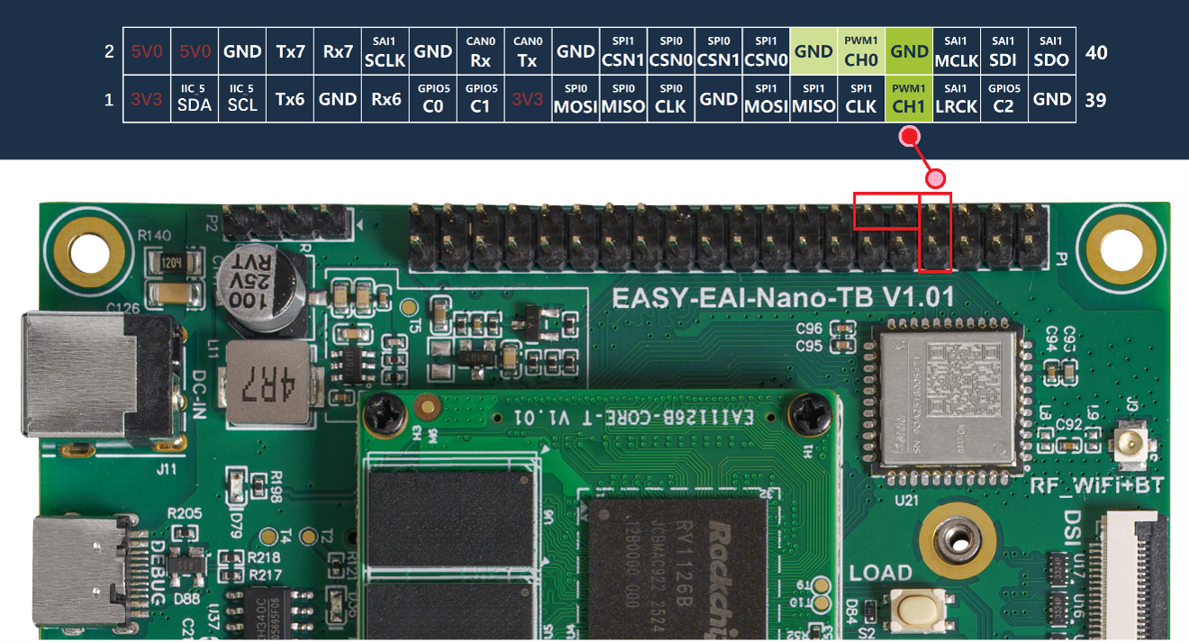
PWM Resources of the Development Board
5.1.2 Finding PWM Nodes
The PWM resource table of the rv1126b is as follows:
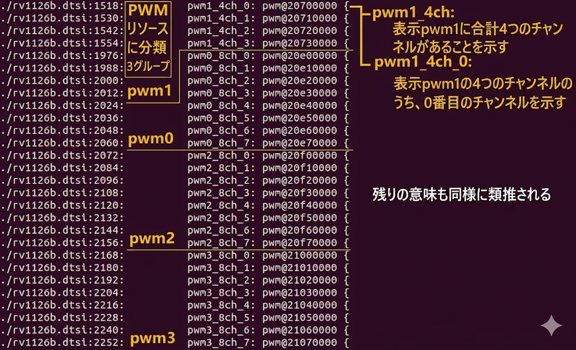
Finding PWM Nodes
-
[PWM1 CH0] corresponds to pwm1_4ch_0, and the register address is 20700000.
-
[PWM1 CH1] corresponds to pwm1_4ch_1, and the register address is 20710000.
After the PWM driver is loaded successfully, under /sys/class/pwm/ in the file system, PWM nodes (pwmchip*) are generated. You can use the following command to check the correspondence between PWM nodes and PWM resources.
-
The node corresponding to [PWM1 CH0] is [pwmchip1].
-
The node corresponding to [PWM1 CH1] is [pwmchip2].
5.1.3 Operating PWM Nodes
The following is an example of operating [PWM1 CH0]:
First, use the command to go to pwmchip1 controller (/sys/class/pwm/pwmchip1), where you can see the following contents:
cd /sys/class/pwm/pwmchip1ls-
export: used to export the PWM timer device.
-
unexport: used to release the PWM timer device.
Writing 0 to the /export file enables the PWM timer and generates the pwm0 directory.
echo 0 \> export
Operating PWM Nodes
pwm0 After entering the timer directory, you can configure various attributes such as the period and duty cycle.
cd pwm0
Operating PWM Nodes
echo 1000000 > period ## set the number of pulses in one timer period (period time)echo 500000 > duty_cycle ## set the number of Low-level pulses in one timer period (active time)echo 1 > enable ## enable the PWM timerecho 0 > enable ## disable the PWM timerConversely, writing 0 to the unexport file closes the PWM timer and deletes the pwm0 directory at the same time.
cd ..echo 0 > unexport
Operating PWM Nodes
Need to modify the figure
5.2. Quick Start
5.2.1 Preparing the Development Environment
On the PC-side Ubuntu system, run the run script to enter the EASY-EAI compilation environment. The details are as follows.
cd ~/develop_environment./run.sh 22045.2.2 Downloading the Source Code and Compiling the Sample
First, run the following commands in the background terminal of the virtual machine to create the management directory for the peripheral sample source code:
cd ~/develop_environment./run.sh 2204Download the sample program:
For example, download the sample program to “PC\D:” (there is no specific requirement; any location chosen by the user is acceptable).
Then copy the downloaded sample to the file system of the virtual machine. Refer to the figure below for the procedure.
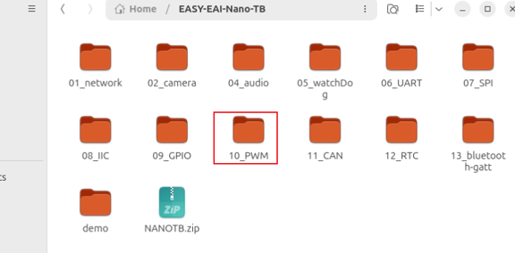
Downloading the Source Code and Compiling the Sample
Finally, go to the corresponding sample directory and run the compilation operation. The specific commands are as follows:
cd EASY-EAI-Nano-TB/demo/10_PWM./build.sh💡 Note :Because the dependent libraries are located on the board, the /mnt mount must be kept during cross-compilation.
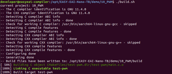
Downloading the Source Code and Compiling the Sample
After compilation succeeds, an executable program named test-pwm is generated in the Release directory and automatically placed in the /userdata/ directory of the development board.
5.2.3 Running the Sample
Access the board background through serial-port debugging or SSH, and go to the directory where the sample is located:
cd /userdata
Running the Sample
Run the following command to start the PWM output demo:
sudo ./test-pwmThe execution result is as follows.
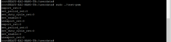
Running the Sample
The waveform captured by the oscilloscope is shown in the figure below:
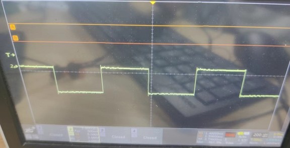
Running the Sample
5.3. C Language Usage Example
This is a C-language usage example for PWM. The code path is 10_PWM/test-pwm/main.c Use it as a coding reference. The following code shows the operation flow for initializing the PWM controller, adjusting the period, setting the duty cycle, and releasing resources:
int main(int argc, const char** argv){    int ret;
    ret = pwm_init("pwmchip1", "0");    printf("export_ret:%d\n", ret);
    ret = pwm_set_attr("pwmchip1", "0", "period", "1000000");    printf("set_period_ret:%d\n", ret);
    ret = pwm_set_attr("pwmchip1", "0", "duty_cycle", "500000");    printf("set_duty_cycle_ret:%d\n", ret);
    ret = pwm_set_enable("pwmchip1", "0", "1");    printf("set_enable:%d\n", ret);
    ret = pwm_release("pwmchip1", "0");    printf("unexport_ret:%d\n", ret);    //======================================================================
    ret = pwm_init("pwmchip2", "0");    printf("export_ret:%d\n",ret);
    ret = pwm_set_attr("pwmchip2", "0", "period", "1000000");    printf("set_period_ret:%d\n",ret);
    ret = pwm_set_attr("pwmchip2", "0", "duty_cycle", "500000");    printf("set_duty_cycle_ret:%d\n",ret);
    ret = pwm_set_enable("pwmchip2", "0", "1");    printf("set_enable:%d\n",ret);
    ret = pwm_release("pwmchip2", "0");    printf("unexport_ret:%d\n",ret);    //======================================================================
    return 0;}
In the code, pwm_init(), pwm_set_attr(), pwm_set_enable(), pwm_release() are wrapper functions that encapsulate system calls for easier use. The specific implementation is described in 10_PWM/test-pwm/main.c.
6.CAN Interface
6.1. CAN Overview
The main purpose of using Socket CAN is to provide user-space applications with a socket interface based on the Linux network layer.
Unlike the well-known TCP/IP protocol and Ethernet, the CAN bus does not have MAC-layer addresses like Ethernet and is used only for broadcasting. The CAN ID is used only for arbitration on the bus, so it must be unique on the bus. When designing a CAN-ECU (Electronic Control Unit) network, the CAN message ID can be mapped to a specific ECU. Therefore, the CAN message ID can be used as the source address.
6.1.1 CAN Resources of the Development Board
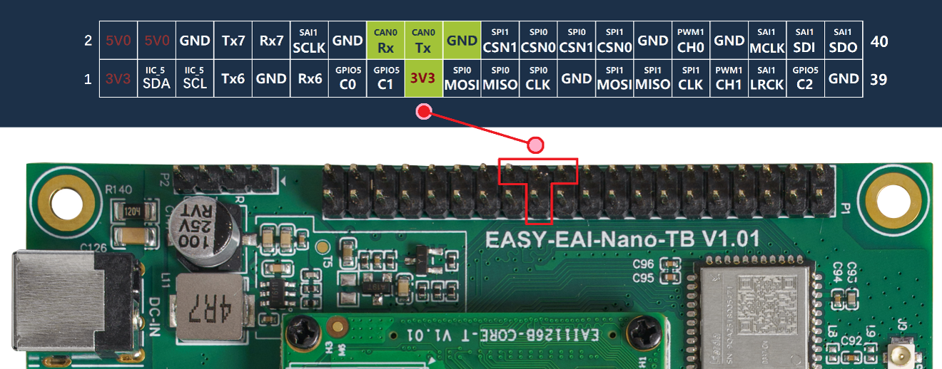
CAN Resources of the Development Board
6.1.2 Hardware Connection
Normally, the CAN signal output from the CPU is a TTL signal rather than a differential signal. Therefore, a module is required to convert the CAN TTL signal into a CAN differential signal. The specific wiring diagram is as follows.
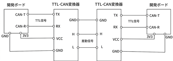
Hardware Connection
6.2. Quick Start
6.2.1 Preparing the Development Environment
On the PC-side Ubuntu system, run the run script to enter the EASY-EAI compilation environment. The details are as follows.
cd ~/develop_environment./run.sh 22046.2.2 Downloading the Source Code and Compiling the Sample
First, run the following commands in the background terminal of the virtual machine to create the management directory for the peripheral sample source code:
cd /optmkdir -p EASY-EAI-Nano-TB/demoDownload the sample program:
For example, download the sample program to “PC\D:” (there is no specific requirement; any location chosen by the user is acceptable).
Then copy the downloaded sample to the file system of the virtual machine. Refer to the figure below for the procedure.
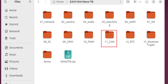
Downloading the Source Code and Compiling the Sample
Finally, go to the corresponding sample directory and run the compilation operation. The specific commands are as follows:
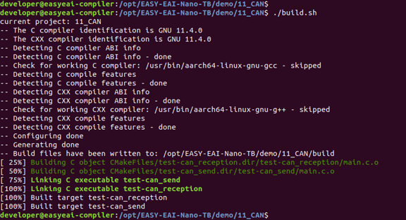
cd EASY-EAI-Nano-TB/demo/11_CAN./build.sh💡 Note : Because the dependent libraries are located on the board, the /mnt mount must be kept during cross-compilation.
Downloading the Source Code and Compiling the Sample
After compilation succeeds, two demo programs, test-can_send for the sender and test-can_reception for the receiver, are generated and automatically placed in the /userdata/ directory of the development board.
- This sample requires two boards for the send/receive test, so the above steps must be repeated on both boards.
6.2.3 Running the Sample
Access the board background through serial-port debugging or SSH, and go to the directory where the sample is located:
cd /userdata
Running the Sample
First, run the sender on the first board. The command is as follows:
sudo ./test-can-sendNext, run the receiver on [the other] board. The command is as follows:
cd /userdatasudo ./test-can-receptionThe execution result of the [receiver] is as follows.

Running the Sample
For detailed API descriptions and API calls (the source code of this sample), refer to the following explanation.
6.3. CAN Operation API Description
6.3.1 Creating a Socket CAN Socket
The function prototype for creating a Socket CAN socket is as follows.
int socket(int domain, int type, int protocol);The detailed description is as follows.
| Item | Content |
|---|---|
| Function name | socket() |
| Header file | <sys/socket.h> |
| Input parameters | Domain (domain): AF_CAN (or PF_CAN)Type (type): SOCK_RAWProtocol (protocol): CAN_RAW |
| Return value | Success: file descriptor (fd) Failure: -1 |
| Notes | None |
6.3.2 Specifying the Local Network Interface Address
The function prototype for specifying the local network interface address is as follows.
int ioctl(int fd, unsigned long request, ...);The detailed description is as follows.
ioctl() function
| Item | Content |
|---|---|
| Function name | ioctl() |
| Header file | <sys/ioctl.h> |
| Input parameters | sockfd: file descriptor (fd) created by the socket() functionRequest: control command |
| Return value | Success: 0Failure: -1 |
| Notes | When using ioctl to obtain the address of the local network interface, the ifreq structure must be used. |
struct ifreq structure
| Item | Content |
|---|---|
| Structure name | struct ifreq |
| Header file | <linux/if.h> |
| Notes | It is used to obtain the index (ifr_ifindex) of the CAN device when calling the ioctl() function. There is no need to pay special attention to the other parameters. |
6.3.3 Binding the Address Structure
The function prototype for binding the address structure is as follows.
int bind(int sockfd, const struct sockaddr \*addr, socklen_t addrlen);| Item | Content |
|---|---|
| Function name | bind() |
| Header file | <sys/socket.h> |
| Input parameters | sockfd: file descriptor (fd) created by the socket() functionaddr: SocketCAN address structure ( struct sockaddr_can, defined in <linux/can.h>)addrlen: address length |
| Return value | Success: 0Failure: -1 |
| Notes | None |
6.3.4 Setting the CAN Filter
The function prototype for setting the CAN filter is as follows.
int setsockopt(int sockfd, int level, int optname, const void \*optval, socklen_t optlen);The detailed description is as follows.
setsockopt() function
| Item | Content |
|---|---|
| Function name | setsockopt() |
| Header file | <sys/socket.h> |
| Input parameters | level: level at which the option is defined (commonly used: SOL_SOCKET, IPPROTO_TCP, SOL_CAN_RAW)optname: option to set optval: pointer to the buffer containing the new value to set for the option optlen: optval buffer length |
| Return value | Success: 0Failure: -1 |
| Notes | The filter structure struct can_filter (defined in <linux/can.h>) must be used. |
struct can_filter structure
| Item | Content |
|---|---|
| Structure name | struct can_filter |
| Header file | <linux/can.h> |
| Parameters | can_id: message ID can_mask: filter mask |
| Notes | The filtering rule is as follows:(can_id of the received data frame) & mask == can_id & maskmask is defined in <linux/can.h> and is selected according to the frame type to receive. |
6.3.5 CAN Message Format Definition
The CAN message format definition is as follows.
| Item | Content |
|---|---|
| Structure name | struct can_frame |
| Header file | <linux/can.h> |
| Parameters | can_id: message ID can_dlc: data length Data[]: array for storing data |
| Notes | By default, standard frames are sent. To send remote frames or error frames, you need to manipulate the message ID. (Example: can_id = 0x1) |
6.4. CAN Communication Sample Program
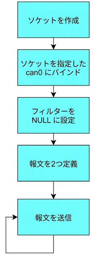
The sample source code for the [sender] is located at 11_CAN/test-can_send/main.c. The operation flow is shown in the figure.
CAN Communication Sample Program
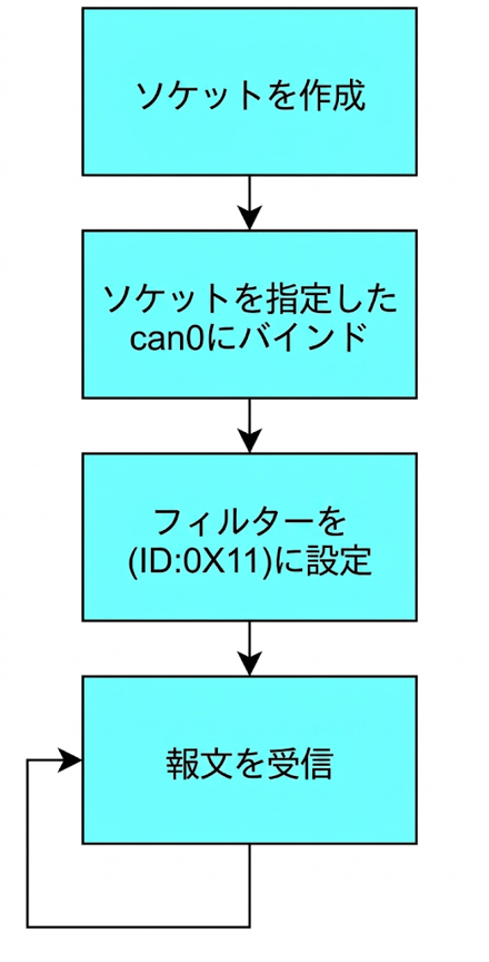
The sample source code for the [receiver] is located at 11_CAN/test-can_reception/main.c. The operation flow is shown in the figure.
CAN Communication Sample Program
The reference sample code is as follows.
Sender Sample:
/* Set the CAN0 baud rate to 500000 bps / #define ip_cmd_set_can_params “ip link set can0 type can bitrate 500000 triple-sampling on” / Start CAN0 / #define ip_cmd_open “ifconfig can0 up” / Stop CAN0 */ #define ip_cmd_close “ifconfig can0 down”
int main(){    int fd, nbytes;    struct sockaddr_can addr;    struct ifreq ifr;    struct can_frame frame[2] = {{0}};
    system(ip_cmd_close);    system(ip_cmd_set_can_params);    system(ip_cmd_open);
    fd = socket(PF_CAN, SOCK_RAW, CAN_RAW); // create the socket    strcpy(ifr.ifr_name, "can0");    ioctl(fd, SIOCGIFINDEX, &ifr);          // specify the can0 device
    addr.can_family = AF_CAN;    addr.can_ifindex = ifr.ifr_ifindex;    bind(fd, (struct sockaddr *)&addr, sizeof(addr)); // bind the socket to can0
    // Disable the filtering rule. This process does not receive messages and is only responsible for sending    setsockopt(fd, SOL_CAN_RAW, CAN_RAW_FILTER, NULL, 0);
    // Generate two messages    frame[0].can_id = 0x11;    frame[0].can_dlc = 1;    frame[0].data[0] = 'Y';
    frame[1].can_id = 0x22;    frame[1].can_dlc = 1;    frame[1].data[0] = 'N';
    // Send the two messages in a loop    while(1)    {        nbytes = write(fd, &frame[0], sizeof(frame[0])); // send frame[0]        printf("write ret:%d\n", nbytes);        if(nbytes != sizeof(frame[0])) {            printf("Send Error frame[0]!\n");            break; // send error; exit        }        sleep(1);
        nbytes = write(fd, &frame[1], sizeof(frame[1])); // send frame[1]        if(nbytes != sizeof(frame[1])) {            printf("Send Error frame[1]!\n");            break;        }        sleep(1);    }    close(fd);    return 0;}
Receiver Sample:
/* Set the CAN0 baud rate to 500000 bps */#define ip_cmd_set_can_params  "ip link set can0 type can bitrate 500000 triple-sampling on"/* Start CAN0 */#define ip_cmd_open            "ifconfig can0 up"/* Stop CAN0 */#define ip_cmd_close           "ifconfig can0 down"
int main(){    int fd, nbytes;    struct sockaddr_can addr;    struct ifreq ifr;    struct can_frame frame;    struct can_filter rfilter[1];
    system(ip_cmd_close);    system(ip_cmd_set_can_params);    system(ip_cmd_open);
    fd = socket(PF_CAN, SOCK_RAW, CAN_RAW); // create the socket    strcpy(ifr.ifr_name, "can0");    ioctl(fd, SIOCGIFINDEX, &ifr);          // specify the can0 device
    addr.can_family = AF_CAN;    addr.can_ifindex = ifr.ifr_ifindex;    bind(fd, (struct sockaddr *)&addr, sizeof(addr)); // bind the socket to can0
    // Define the receiving rule. Receive only messages whose identifier is 0x11    rfilter[0].can_id = 0x11;    rfilter[0].can_mask = CAN_SFF_MASK;
    // Set the filtering rule    setsockopt(fd, SOL_CAN_RAW, CAN_RAW_FILTER, &rfilter, sizeof(rfilter));
    while(1)    {        nbytes = read(fd, &frame, sizeof(frame)); // receive the message        // display the message        if(nbytes > 0) {            printf("ID=0x%X DLC=%d data[0]=0x%X\n", frame.can_id, frame.can_dlc, frame.data[0]);        }    }    close(fd);    return 0;}