
Switch OTG to USB Disk Mode
1.1. Introduction
1.1. 1 Switch OTG to USB Mode
By switching the OTG USB mode, the development board can function both as a HOST and as a Device (such as a USB disk), improving data transfer efficiency.
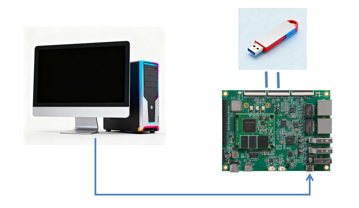
1.1.1 Switch OTG to USB Mode Figure 1
1.1.2 Basic Concept of OTG
OTG is the abbreviation for “USB On-The-Go”, a technical standard that extends USB functionality and was released by the USB standardization organization in 2001. Its core purpose is to break through the limitation of traditional USB, where the host and device roles are fixed, and to improve connection and data exchange between different devices. As a result, devices (development boards, smartphones, tablets, etc.) can either act as hosts to connect peripheral devices or act as devices (slaves) to be accessed by other equipment.
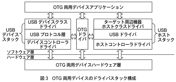
11.1. 2 Basic Concept of OTG Figure 2
1.2. Linux Kernel Driver Configuration and Compilation
1.2.1 Upgrade to the Latest Firmware
1.2.2 Download the Ubuntu System SDK
1.2.3 Kernel Modification
Device Drivers --->[ ] USB support ---><*> DesignWare USB2 DRD Core Support (RV1126B supports this core driver by default)DWC2 Mode Selection (Dual Role mode) ---> (Select dual-role mode)<*> USB Gadget Support --->(Keep the default) Set Maximum VBUS Power usage (2-500 mA) to 500(Keep the default) Set Number of storage pipeline buffers to 2<M> USB functions configurable through configfs [*] Mass storage (Enable the mass storage function) <M> Gadget Filesystem< > Function Filesystem<M> Mass Storage GadgetFind the corresponding driver configuration in the kernel and add it to RV1126b_eai.config` as shown below.
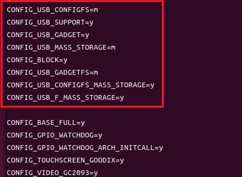
11.2. 3 Kernel Modification Figure 3
💡 Note: RV1126b_eai.config` is located in the kernel_dev/arch/arm64/configs directory.
1.2.4 Compile and Generate Kernel Modules
💡 Note: Remember to transfer lib_modules.tar.gz` to the development board and extract it. After compilation and update are complete, the following four important modules will be generated in the specified directory on the development board.
drivers/usb/gadget/libcomposite.kodrivers/usb/gadget/legacy/gadgetfs.kodrivers/usb/gadget/legacy/g_mass_storage.kodrivers/usb/gadget/function/usb_f_mass_storage.koDirectory: /lib/modules/6.1.141/kernel/drivers/usb/…
[Before compilation and update]

1.2.4 Compile and Generate Kernel Modules Figure 4
[After compilation and update]
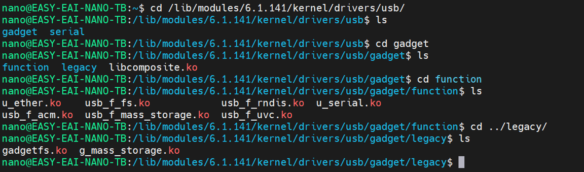
1.2.4 Compile and Generate Kernel Modules Figure 5
💡 Note: After the update is complete, adb will be disabled. Use the serial console or ssh for debugging.
1.3. OTG USB Disk Switching Configuration
1.3.1 Create a USB Disk Image File and Mount Point
Run the following command to create a 1.6 GB virtual USB disk image (it can be adjusted according to the memory size of the RV1126B. If memory is limited, reduce the count value. For example, count=800 creates a 0.8 GB image):
dd if=/dev/zero of=/userdata/mydisk/udisk.img bs=1M count=1600Install the required dependency tools:
sudo apt-get update && sudo apt-get install dosfstools -yFormat the image as vfat so that it can be recognized by a PC:
mkfs.vfat /userdata/mydisk/udisk.img1.3.2 Load Modules and Start USB Disk Simulation
Bind the image file to a loop device (RV1126B supports the `loop7` device, so no additional configuration is required):
sudo losetup /dev/loop7 /userdata/mydisk/udisk.imgLoad the kernel modules generated during compilation in sequence:
sudo insmod gadgetfs.kosudo insmod libcomposite.kosudo insmod usb_f_mass_storage.ko💡 Note: The commands above do not display any message after execution. Be sure to run them in the order shown above.
Directory: /lib/modules/6.1.141/kernel/drivers/usb/…
Create a mount point for the image file:
sudo mkdir /mnt/udiskMount the image file to the created directory:
sudo mount /dev/loop7 /mnt/udiskStart the USB disk simulation function (after execution, the PC will display a notification that a new USB device has been detected):
sudo insmod g_mass_storage.ko file=/dev/loop7 removable=11.4. Function Test
Basic data sending and receiving test
1. PC side: Connect the Nano-TB RV1126B development board’s OTG interface to the PC with a USB cable. You can read and write files just like using a normal USB disk.
2. Development board side: After entering the /mnt/udisk directory, you can check the files copied from the PC to the USB disk. After writing files to this directory, unplugging and reconnecting the USB cable will make them appear on the PC side as well.
1.4.1 Notes
1. If files written on the PC are not displayed on the development board:
sudo umount /mnt/udisk && sudo mount /dev/loop7 /mnt/udiskRun the command above to remount it.
2. If files written on the development board are not displayed on the PC:
Unplug and reconnect the USB cable once to refresh it.
3. When mass storage mode is started and the development board is used as a USB disk, **the adb function will be disabled**.
2. USB OTG Mode
2.1. Overview of USB OTG
USB OTG (On-The-Go) is an extension standard of the USB protocol that solves the limitation of traditional USB, which only supports one-way “HOST-Device (Peripheral/Device)” connections. The USB OTG interface of the EASY-EAI-Nano-TB development board supports flexible switching between HOST mode and Peripheral mode. It can be configured as OTG mode by default, and the operating mode can be quickly changed using system commands to meet device connection needs in various scenarios, such as connecting to USB disks, keyboards, mice, and other peripherals, or communicating with a PC as a slave device.
2.2. Default OTG Mode
Introduction to EASY EAI Nano USB resources
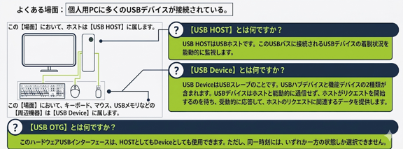
2.2. Default OTG Mode Figure 1
When using the following firmware for development, it is configured as USB OTG mode by default:
Check the current OTG mode:
cat /sys/devices/platform/21400000.usb2-phy/otg_mode2.2.1 Switch to HOST Mode
However, in certain scenarios, such as when you want to connect and use a USB disk or other USB device, you need to switch the USB interface to USB HOST mode. In that case, follow the steps below to switch it. First, [remove all] devices connected to the USB interface. Then use the [serial console (serial debugging)] (baud rate: 1500000) to log in to the board console. The username is nano, and the password is 123456`. Next, run the following command to switch the USB interface to HOST mode:
echo host \> /sys/devices/platform/21400000.usb2-phy/otg_modeCheck the current HOST mode:
cat /sys/devices/platform/21400000.usb2-phy/otg_mode
2.2.1 Switch to HOST Mode Figure 2
Use a USB device (using a USB disk as an example) for verification. After inserting the USB disk, you can verify it using the following two methods:
1 lsusb command

2.2.1 Switch to HOST Mode Figure 3
2 lsblk command
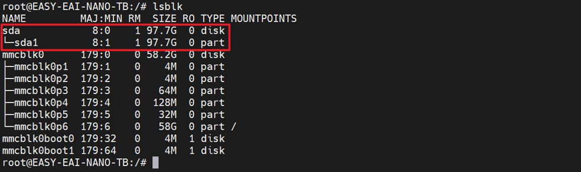
12.2.1 Switch to HOST Mode Figure 4
2.2.2 Switch to Device Mode
If you want to switch back to USB Device mode for use, you can switch to Device mode using an operation similar to switching to HOST mode. First, as before, [remove all] devices connected to the USB interface. Then run the following command to switch to USB Device mode:
echo peripheral \> /sys/devices/platform/21400000.usb2-phy/otg_mode
2.2.2 Switch to Device Mode Figure 5
Finally, connect the ADB cable and use `adb shell` to enter the ADB environment and verify it.
💡 Note: When switching to Device mode, ADB does not become available immediately. You need to wait about 1 minute until the adb shell command can access the ADB environment.