
Device Software Manual
1. Ethernet Port
1.1. Overview of Network Configuration
This document describes the basic network configuration of the system. It also provides a simple sample that uses the yaml-cpp library to modify network settings, for cases where network settings need to be changed from within a program.
1.1.1 Netplan and YAML Files
1.1.1.1 Background
The runtime environment of this analysis system uses Ubuntu 22.04. Starting from Ubuntu 18.04, Ubuntu uses netplan instead of ifupdown for network configuration, so static IP settings in /etc/network/interfaces are no longer valid. Therefore, network settings must be configured in /etc/netplan/xxxx.yaml, and you need to understand the basic syntax of YAML files.
1.1.1.2 Netplan Network Configuration Techniques
Please read “Netplan Network Configuration Techniques”, which explains the basic syntax and precautions in detail.
1.1.2 How to Operate the Ethernet Card
1.1.2.1 Network Port Wiring
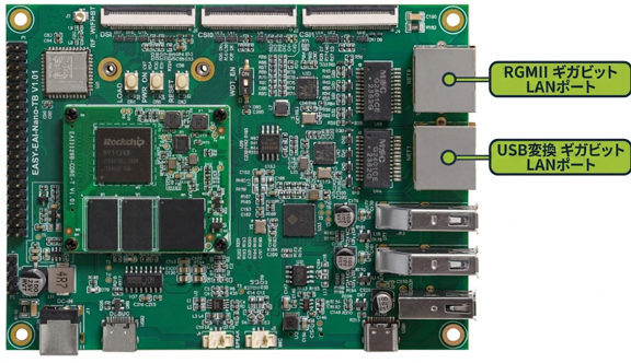
Network Port Wiring
1.1.2.2 Changing Ethernet Settings
Use the following command to check the storage path for the development board network settings. You will find four configuration files. Among them, 50-eth0-init.yaml is the netplan configuration related to [NET0], and 51-eth1-init.yaml is the netplan configuration related to [NET1].
ls /etc/netplan/
Changing Ethernet Settings
The contents are as follows:
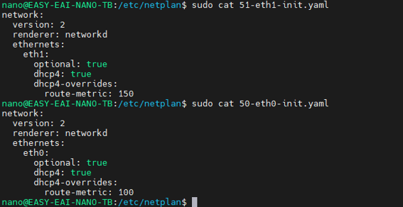
Changing Ethernet Settings
For details about the settings for [DHCP] and [Static IP], refer to the figure.
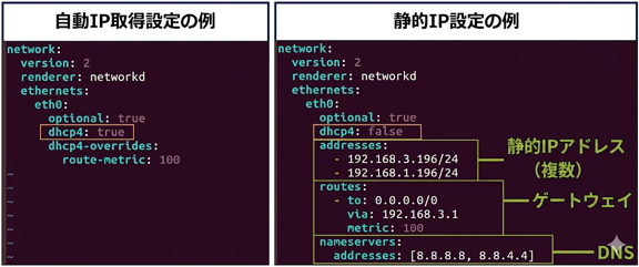
Changing Ethernet Settings
💡 Note: In both [DHCP] and [Static IP] cases, a LAN cable must be connected for the settings to take effect. Only after connecting the cable can you use the ifconfig command to view the assigned IP address.
Network settings can be split into separate files or written in the same YAML file. The following example combines NET0 and NET1 into one file (99_config.yaml), configures eth0 as DHCP, and configures eth1 with a static IP:
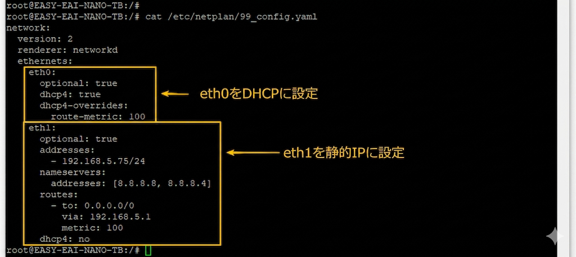
Changing Ethernet Settings
After modifying the YAML file, run the following commands to apply the update:
sudo netplan generatesudo netplan apply1.2. Quick Start
1.2.1 Preparing the Development Environment
On the Ubuntu system on the PC side, execute the run
script to enter the EASY-EAI compilation environment. The details are as follows.
cd ~/develop_environment./run.sh 22041.2.2 Downloading the Source Code and Compiling the Sample
First, run the following commands in the background terminal of the virtual machine to create the management directory for the peripheral sample source code:
cd /optmkdir -p EASY-EAI-Nano-TB/demoFor example, download the sample program to “PC\D:” (this is not required; any location chosen by the user is acceptable).
Then copy the downloaded sample to the file system of the virtual machine.
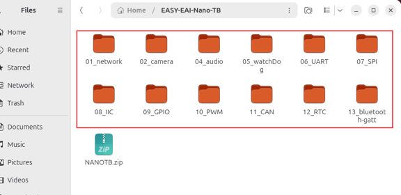
Downloading the Source Code and Compiling the Sample
Finally, go to the corresponding sample directory and perform the compilation. The specific commands are as follows:
cd EASY-EAI-Nano-TB/demo/01_network./build.sh💡 Note: Because the dependent libraries are placed on the board, the /mnt mount must be maintained during cross-compilation.
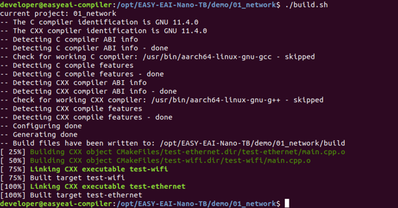
Downloading the Source Code and Compiling the Sample
If an error occurs, install the libyaml-cpp-dev library [on the development board]:

Downloading the Source Code and Compiling the Sample
sudo apt-get install libyaml-cpp-dev1.2.3 Running the Sample
Access the board background through serial-port debugging or SSH, and move to the directory where the sample is located:
cd /userdata
Running the Sample
The command to run the sample is as follows:
./test-ethernetThis demo changes the eth0 configuration to [Static IP: 192.168.1.170]. If eth0 is mounted in the compilation environment, or if you are debugging through SSH and the IP obtained by DHCP before the change was not 192.168.1.170, all connections will be disconnected after this sample code finishes running.
1.2.4 Execution Result
The execution result is shown in the figure.
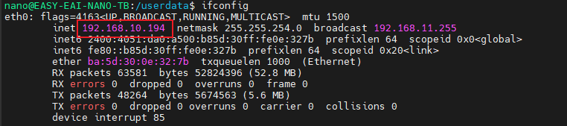
Execution Result
The configuration file is also modified at the same time.
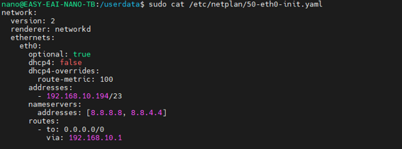
Execution Result
1.3 Operation Example
The sample code is located at 01_network/test-ethernet/main.cpp.
1.3.1 Sample Source Code
The following code is an example of setting the IP address, DNS, and gateway parameters of eth0. Use it as a coding reference:
int main() {    // Load the YAML file    YAML::Node config = YAML::LoadFile("/etc/netplan/50-eth0-init.yaml");
    // =====================Modify eth0 parameters==========================    // Disable DHCP    config["network"]["ethernets"]["eth0"]["dhcp4"] = "false";
    // Change the IP address of eth0    // Method 1: Write to the first position at a fixed location    config["network"]["ethernets"]["eth0"]["addresses"][0] = "192.168.1.170/24";
    // Method 2: Insert by appending    // Enter the IP address and subnet mask    // std::string eth0_ip_str = "192.168.1.171";    // std::string eth0_mask_str = "255.255.255.0";    // std::string eth0_cidr = mask_transition_cidr(eth0_ip_str, eth0_mask_str);    // config["network"]["ethernets"]["eth0"]["addresses"].push_back(eth0_cidr);
    // Change the DNS address of eth0    YAML::Node addresses_eht0_dns = YAML::Load("[8.8.8.8,8.8.4.4]"); // [8.8.8.8, 8.8.4.4] is a sequence, so conversion is required    config["network"]["ethernets"]["eth0"]["nameservers"]["addresses"] = addresses_eht0_dns;
    // Change the route (routes) address of eth0    config["network"]["ethernets"]["eth0"]["routes"][0]["to"] = "0.0.0.0/0";    config["network"]["ethernets"]["eth0"]["routes"][0]["via"] = "192.168.1.1";    config["network"]["ethernets"]["eth0"]["routes"][0]["metric"] = "100";
    #if 0    // =====================Modify eth1 parameters=========================    config["network"]["ethernets"]["eth1"]["dhcp4"] = "false";    // Method 1: Write to the first position at a fixed location    config["network"]["ethernets"]["eth1"]["addresses"][0] = "192.168.1.172/24";
    // Method 2: Insert by appending    // std::string eth1_ip_str = "192.168.1.171";    // std::string eth1_mask_str = "255.255.255.0";    // std::string eth1_cidr = mask_transition_cidr(eth1_ip_str,eth1_mask_str);    // config["network"]["ethernets"]["eth1"]["addresses"].push_back(eth1_cidr);
    YAML::Node addresses_eht1_dns = YAML::Load("[8.8.8.8,8.8.4.4]");    config["network"]["ethernets"]["eth1"]["nameservers"]["addresses"] = addresses_eht1_dns;    config["network"]["ethernets"]["eth1"]["routes"][0]["to"] = "0.0.0.0/0";    config["network"]["ethernets"]["eth1"]["routes"][0]["via"] = "192.168.1.1";    config["network"]["ethernets"]["eth1"]["routes"][0]["metric"] = "150";    #endif
    // ==============Write the modified YAML document back to the file==================    std::ofstream fout("/etc/netplan/50-eth0-init.yaml");    fout << config;    fout.close();
    // =======================Restart the network card===============================    system("sudo netplan generate");    system("sudo netplan apply");
    return 0;}
2. Wi-Fi STA
2.1 Overview of Network Configuration
This document describes the basic network configuration of the system. It also provides a simple sample that uses the yaml-cpp library to modify network settings, for cases where network settings need to be changed from within a program.
2.1.1 Netplan and YAML Files
2.1.1.1 Background
The runtime environment of this analysis system uses Ubuntu 22.04. Starting from Ubuntu 18.04, Ubuntu uses netplan instead of ifupdown for network configuration, so static IP settings in /etc/network/interfaces are no longer valid. Therefore, network settings must be configured using YAML files in the /etc/netplan/ directory, and you need to understand the basic syntax of YAML files.
2.1.1.2 Netplan Network Configuration Techniques
2.1.2 How to Operate Wi-Fi
2.1.2.1 Connecting the Wi-Fi Antenna
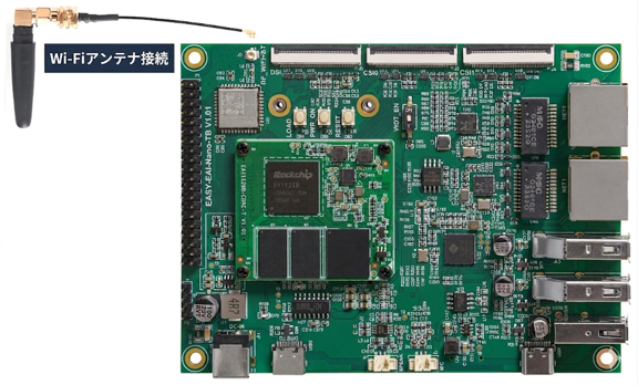
Connecting the Wi-Fi Antenna
2.1.2.2 Changing Wi-Fi Network Settings
Use the following command to check the storage path for the development board network settings. You will find four configuration files. Among them, 52-wlan0-init.yaml is the netplan configuration related to the [Wi-Fi network card].
ls /etc/netplan/
Changing Wi-Fi Network Settings
The following is an example of configuring wlan0 as DHCP:
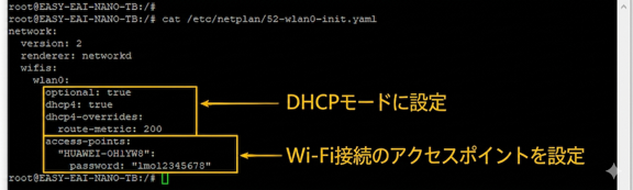
Changing Wi-Fi Network Settings
For details about each part of the network card configuration, refer to the figure below:
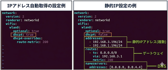
Changing Wi-Fi Network Settings
After modifying the YAML file, run the following commands to apply the update:
sudo netplan generatesudo netplan apply2.2 Quick Start
2.2.1 Preparing the Development Environment
On the Ubuntu system on the PC side, execute the run script to enter the EASY-EAI compilation environment. The details are as follows.
cd ~/develop_environment./run.sh 22042.2.2 Downloading the Source Code and Compiling the Sample
First, run the following commands in the background terminal of the virtual machine to create the management directory for the peripheral sample source code:
cd /optmkdir -p EASY-EAI-Nano-TB/demoFor example, download the sample program to “PC\D:” (this is not required; any location chosen by the user is acceptable).
Then copy the downloaded sample to the file system of the virtual machine. Refer to the figure below for the procedure.
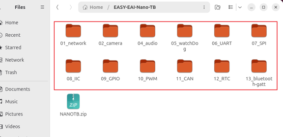
Downloading the Source Code and Compiling the Sample
Finally, go to the corresponding sample directory and perform the compilation. The specific commands are as follows:
cd EASY-EAI-Nano-TB/demo/01_network./build.sh💡 Note: Because the dependent libraries are placed on the board, the /mnt mount must be maintained during cross-compilation.
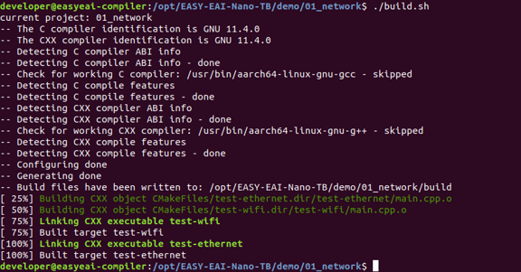
Downloading the Source Code and Compiling the Sample
If the following error occurs, install the libyaml-cpp-dev library [on the development board]:

Downloading the Source Code and Compiling the Sample
sudo apt-get install libyaml-cpp-dev2.2.3 Running the Sample
Access the board background through serial-port debugging or SSH, and move to the directory where the sample is located:
cd /userdata
Running the Sample
The command to run the sample is as follows:
./test-wifiThis demo changes the wlan0 configuration to Wi-Fi Station mode and connects to a Wi-Fi AP (access point) named “HUAWEI-0H1YW8”.
2.2.4 Execution Result
After running, if the connection succeeds, the access point assigns an IP address to the development board. The result is shown in the figure below.
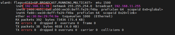
Execution Result
2.3 Operation Example
The sample code is located at 01_network/test-wifi/main.cpp.
2.3.1 Sample Source Code
The following code is an example of configuring the wlan0 access point connection. Use it as a coding reference:
int main() {    // Load the YAML file    YAML::Node config = YAML::LoadFile("/etc/netplan/52-wlan0-init.yaml");
    // =====================Modify Wi-Fi parameters===========================    config["network"]["wifis"]["wlan0"]["dhcp4"] = "true";    config["network"]["wifis"]["wlan0"]["dhcp4-overrides"]["route-metric"] = "200";    config["network"]["wifis"]["wlan0"]["access-points"]["HUAWEI-0H1YW8"]["password"] = "lmo12345678";    // =============================================================
    // Write the modified YAML document back to the file    std::ofstream fout("/etc/netplan/52-wlan0-init.yaml");    fout << config;    fout.close();
    // =======================Restart the network card===============================    system("sudo netplan generate");    system("sudo netplan apply");
    return 0;}
3.Wi-Fi AP
3.1. Overview of This Document
3.1.1 Importance of Wi-Fi AP Mode
Wi-Fi The main value of AP (Access Point) mode is that it turns a device, such as an embedded development board, into a wireless access point, enabling centralized connection of multiple wireless devices and network communication between them. For EASY-EAI series development boards, this mode eliminates dependence on a router and directly provides wireless networking capabilities to devices such as smartphones, PCs, and tablets. It supports scenarios such as data sharing between devices, remote debugging, and collaborative work, and is especially suitable for temporary network construction in environments without a router and for wireless management of embedded devices.
3.2. Configuring Wi-Fi AP Mode
3.2.1 Enabling the wlan1 Interface
- Run the following command to create the wlan1 interface for building AP mode:
sudo echo "Featureid0 create wlan1 ap" \> /sys/ccsys/ccpriv-
Check the status of the wlan1 interface: Run ifconfig. If wlan1 is displayed, it is enabled. If it is not displayed, run ifconfig -a. If it exists there, it means the interface has not been brought up.
-
Bring up the wlan1 interface (run this if it is not up):
sudo ifconfig wlan1 up💡 Note: To avoid SSH disconnection caused by network configuration changes, use ADB or serial-port debugging for the following operations.
3.2.2 Configuring the hostapd Service
hostapd is the core service used to implement AP mode. It manages parameters such as the wireless network SSID, encryption method, and channel.
- Create the directory for storing the hostapd configuration file (if it does not exist):
sudo mkdir -p /etc/wireless- Edit the hostapd configuration file:
sudo vim /etc/wireless/hostapd.conf- Write the following configuration contents (important parameters include explanations):
# Specify the wireless interface to use (example: wlan0)interface=wlan1
# Use the nl80211 driver (most modern systems use nl80211)driver=nl80211
# Set the software AP name (SSID)ssid=EASY-EAI-TEST
# Wireless mode: g means 2.4 GHz 802.11g (for 5 GHz, a mode can be used, but the configuration may differ slightly)hw_mode=g
# Set the wireless channel (choose a channel with less interference, such as 6)channel=6
# MAC address filtering: 0 means filtering is not usedmacaddr_acl=0
# Authentication algorithm (1 means only open-system authentication is used)auth_algs=1
# Whether to hide the SSID: 0 means broadcasting the SSIDignore_broadcast_ssid=0
# Enable WPA encryption. WPA2 is recommended (wpa=2 means only WPA2 is supported)wpa=2
# Set the WPA2 pre-shared key (length: 8 to 63 characters)wpa_passphrase=12345678
# Specify WPA-PSK as the key management methodwpa_key_mgmt=WPA-PSK
# Specify the encryption algorithm. Generally, using only CCMP (AES) is recommended for higher security.# TKIP is compatible with some older devices but has lower security. Multiple algorithms can be listed here at the same time for compatibility.wpa_pairwise=CCMP TKIPrsn_pairwise=CCMP- Save the configuration file and exit Vim (press ESC, type :wq, and press Enter).
3.2.3 Configuring the udhcpd Service
udhcpd is a lightweight DHCP server. It is used to automatically assign IP addresses to devices connected to the AP and ensure network communication between devices.
- Edit the udhcpd configuration file:
sudo vim /etc/wireless/udhcpd.conf- Write the following configuration contents (the IP address range can be adjusted as needed):
# Sample udhcpd configuration file (/etc/udhcpd.conf)
# The start and end of the IP lease block# Set the range of IP addresses that can be assignedstart           192.168.123.20  #default: 192.168.0.20end             192.168.123.254 #default: 192.168.0.254
# The interface that udhcpd will use# Specify the port (interface) on which the DHCP server listensinterface       wlan1           #default: eth0
#Examles# Set network-related parameter informationopt     dns     223.5.5.5option  subnet  255.255.255.0opt     router  192.168.123.1opt     wins    192.168.123.1#option dns     129.219.13.81   # appened to above DNS servers for a total of 3option  domain  localoption  lease   864000          # 10 days of seconds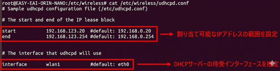
Configuring the udhcpd Service

Configuring the udhcpd Service
- Set the static IP of wlan1 (it must be in the same subnet as the DHCP address range):
💡 Note: To avoid IP address conflicts, the static IP must be set to an address outside the DHCP range.
3.2.4 Starting the Wi-Fi AP Service
- Start the hostapd service in the background (& indicates background execution):
sudo hostapd /etc/wireless/hostapd.conf &- Start the udhcpd service (-S means foreground execution, which is convenient for viewing logs):
sudo udhcpd -S /etc/wireless/udhcpd.conf- If you need to run the udhcpd service in the background, execute the following command:
sudo udhcpd /etc/wireless/udhcpd.conf &- If the command is not found, use the following command to install the tools.
sudo apt-add-repository universe sudo apt update sudo apt install hostapd udhcpd3.3 Function Test
3.3.1 Basic Connection Test
-
Turn on Wi-Fi on wireless devices such as smartphones and PCs.
-
Search for the SSID (in this document, the example is: EASY-EAI-TEST).
-
Enter the configured password (in this document, the example is: 12345678).
-
Connection check: after the connection succeeds, the device obtains a 192.168.123.x network IP address. Try pinging between devices to confirm connectivity.
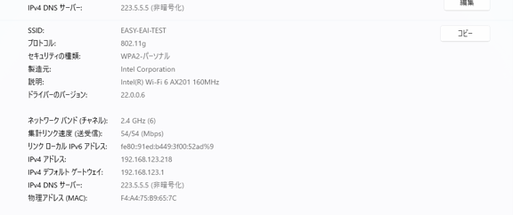
Basic Connection Test
3.3.2 Data Transfer Test
- Development board side: create a test file in the /userdata directory.
sudo echo "WIFI AP Test File" \> /userdata/test_ap.txt- Client side (such as a PC): connect to the development board through SSH or SCP and download the file.
scp root@192.168.123.1:/userdata/test_ap.txt ./- Reverse-direction test: upload a file from the client to the development board and confirm that bidirectional communication is normal.
3.3.3 Notes
- If you change the SSID or password, restart the service after editing hostapd.conf:
sudo pkill hostapd && sudo hostapd /etc/wireless/hostapd.conf &-
After restarting the development board, you need to run the startup command again (you can also create a startup auto-run script).
-
To prevent interface conflicts, do not enable multiple wireless services at the same time.
-
When using the 5 GHz band (hw_mode=a), confirm that the development board hardware supports that band.
4 4G
4.1 Overview of Using the 4G Module
The 4G module must be used together with a SIM card ([standard SIM card] or [IoT SIM card]), so dial-up connection must be performed through AT commands. In addition, in a Linux system it is treated as a network card device, so network configuration management is also required. Because AT commands are used only during network card initialization, this document focuses on network settings related to the 4G module.
4.1.1 Netplan and YAML Files
4.1.1.1 Background
The runtime environment of this analysis system uses Ubuntu 22.04. Starting from Ubuntu 18.04, Ubuntu uses netplan instead of ifupdown for network configuration, so static IP settings in /etc/network/interfaces are no longer valid. Therefore, network settings must be configured using YAML files in the /etc/netplan/ directory, and you need to understand the basic syntax of YAML files.
4.1.1.2 Netplan Network Configuration Techniques
4.1.2 AT Commands
AT commands: The 4G module must use AT commands to configure its operating status and certain parameters. AT commands are essentially serial communication commands. They all start with “AT” and end with “(that is, carriage return)”. After the module starts, the default serial-port settings are: data bits: 8 bits, stop bits: 1 bit, parity: none, and hardware flow control (CTS/RTS). When sending AT commands, note that the serial terminal requires adding “(that is, line feed)” at the end. In Linux systems, sending and receiving are performed through /dev/ttyUSB* device nodes. For AT command transmission, excluding the two characters “AT”, up to 1056 characters (including the final Null character) can be received. The categories and command format are shown in the figure below.

AT Commands
4.1.3 Hardware Interface Description
4.1.3.1 MINI-PCIE
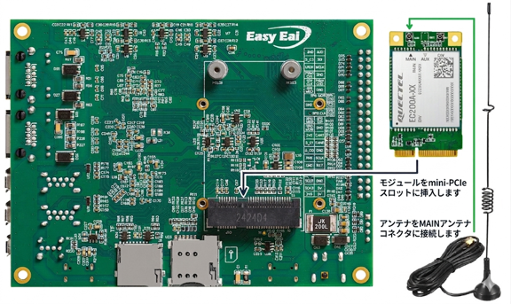
MINI-PCIE
4.1.3.2 SIM Card Interface
-
Standard SIM card: This is the phone SIM card we commonly use. This type of SIM card has no binding relationship with the 4G module.
-
IoT SIM card: It must be bound to a 4G module. One IoT SIM card can be bound to only one 4G module, but multiple IoT SIM cards can be bound to the same 4G module at the same time.
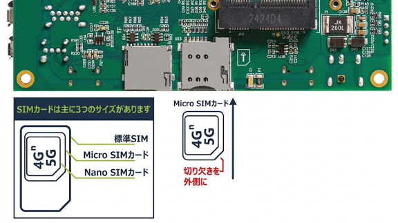
SIM Card Interface
4.2. Dial-Up Connection
4.2.1 Checking the YAML Configuration
Use the following command to check the storage path for the development board network settings. You will find four configuration files. Among them, 61-mobile0-init.yaml is the netplan configuration related to the [4G network card].
ls /etc/netplan/
Checking the YAML Configuration
If it does not exist, you need to create it manually. The following is an example of configuring mobile0 as DHCP:
YAMLnetwork: version: 2 renderer: networkd ethernets: mobile0: optional: true dhcp4: true nameservers: addresses: [8.8.8.8, 8.8.4.4] dhcp4-overrides: route-metric: 250After modifying the YAML file, run the following commands to apply the update:
sudo netplan generatesudo netplan apply4.2.2 Checking Whether the 4G Network Card Is Recognized Normally
Run the lsusb command. If it is recognized normally, Quectel Wireless will be displayed as shown in the figure below.

Checking Whether the 4G Network Card Is Recognized Normally
Next, run the ifconfig command. If it is recognized normally, mobile0 will be displayed as shown in the figure below.
ifconfig
Checking Whether the 4G Network Card Is Recognized Normally
4.2.3 Dial-Up Operation
Control interaction between the system and the 4G module is usually implemented through a USB serial port. Specifically, control interaction is performed by sending AT commands through the USB serial port. Therefore, you first need to check what USB serial-port resources are available.

Dial-Up Operation
Contact the module manufacturer to obtain the “USB Driver Development Guide” and determine which USB serial port the corresponding module uses as the [Modem]. Dial-up operation is performed through this serial port. The details are shown in the figure.
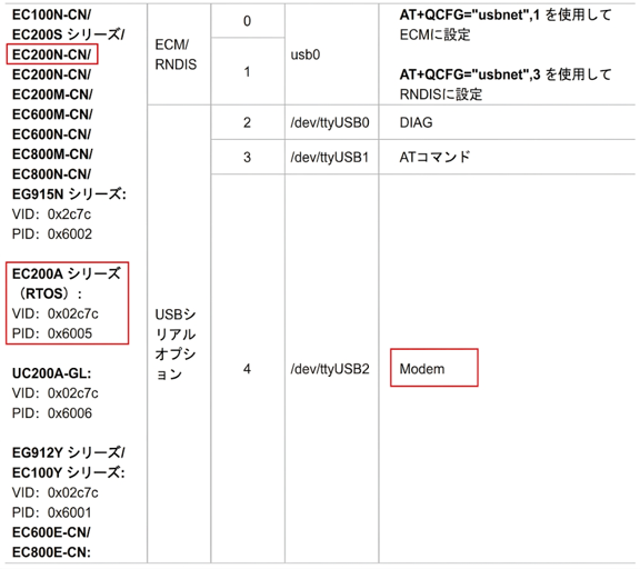
Dial-Up Operation
The dial-up command is one of the AT commands. The specific command is AT+QNETDEVCTL=3,1,1. The dial-up command for EC200N-CN (CAT1) is sent through /dev/ttyUSB2.
The command to run on the development board is as follows:
echo -ne "AT+QNETDEVCTL=3,1,1\n" \> /dev/ttyUSB2-
Automatic dial-up: “AT+QNETDEVCTL=3,1,1\n”
-
Manual dial-up (dial-up is required again after restart): “AT+QNETDEVCTL=1,1,1\n”
If you are logged in as a non-root user, you can send the AT command to /dev/ttyUSB2 using the following command:
echo -ne "AT+QNETDEVCTL=3,1,1\n" \| sudo tee /dev/ttyUSB24.3 Network Connection Test
ifconfig command to check whether an IP address has been assigned to the 4G network card normally.
ifconfig
Network Connection Test
If an IP address has been assigned normally, run the following command to check whether the external network can be accessed:
ping 8.8.8.8 -I mobile0If data is returned from the server, the access is successful.

Network Connection Test
> 💡 Note: If the external network cannot be accessed, check the following:
-
Whether the antenna is connected correctly
-
Whether the 4G signal at the device installation location is good
-
Whether the SIM card is inserted
-
If the SIM card is an IoT SIM card, whether the card has not expired and has not been bound to another device
-
Whether the data allowance (traffic) or balance on the card is sufficient