
System Control, Storage and USB
1. Watchdog
1.1. Checking Watchdog Resources
You can use the ls command to check how many watchdog nodes exist in the system.
ls /dev/watchdog\*
Checking Watchdog Resources
1.2. Quick Start
1.2.1 Preparing the Development Environment
On the Ubuntu system of the PC, run the run script to enter the EASY-EAI compilation environment. The details are as follows.
cd ~/develop_environment./run.sh 22041.2.2 Downloading the Source Code and Compiling the Sample
First, run the following commands in the background terminal of the virtual machine to create the management directory for the peripheral sample source code:
cd /optmkdir -p EASY-EAI-Nano-TB/demoDownload the sample program:
For example, download the sample program to “PC\D:” (there is no restriction; any location selected by the user is acceptable).
Then copy the downloaded sample to the virtual machine file system. Refer to the figure below for the procedure.
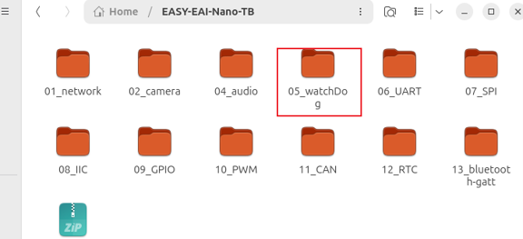
Downloading the Source Code and Compiling the Sample
Finally, go to the corresponding sample directory and perform the compilation operation. The specific commands are as follows:
cd EASY-EAI-Nano-TB/demo/05_watchDog./build.sh💡 Note: Because the dependent libraries are placed on the board, the /mnt mount must be kept during cross-compilation.
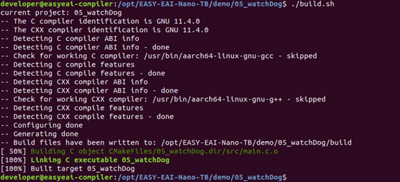
Downloading the Source Code and Compiling the Sample
1.2.3 Running the Sample
Access the board background through serial-port debugging or SSH, and enter the directory where the sample is located:
cd /userdataThe command to run the sample is as follows:
./05_watchDog1.2.4 Execution Result
The execution result is as follows [Note!! Running the demo will reboot the system. Please operate carefully].

Execution Result
If you do not want the system to reboot, you can press 【Ctrl+C】 on the keyboard during execution to stop the watchdog process.
1.3. C Language Usage Example
This is a C language usage example for the watchdog. The code path is 05_watchDog/test-watchDog/main.c. Use it as a reference for coding. The following code shows the basic operation flow of the watchdog timer:
void ctrl_c_handler(){    int ret = wdt_close();    if(ret < 0){        printf("\nFailed to disable the watchdog!!!\n");    }else if(ret == 0){        printf("\nWatchdog disabled successfully!!!\n");    }    exit(0);}
int main(){    int timeout = 30;    int ret = wdt_open(timeout);    if(ret < 0){        printf("Failed to enable the watchdog!!!\n");        return -1;    }    printf("Watchdog enabled successfully. Actual timeout: %d (seconds)\n", ret);
    // Catch the Ctrl+C signal    signal(SIGINT, ctrl_c_handler);
    int feedTimes = 0;    while (1)    {        sleep(3);
        if(5 < feedTimes){            printf("Stop feeding the dog (stop clearing the watchdog)\n");            continue;        }
        if(0 == wdt_feeddog()){            feedTimes++;            printf("Feeding the dog (clearing the watchdog) succeeded!!!\n");        }else{            printf("Feeding the dog (clearing the watchdog) failed!!!\n");        }    }    return 0;}
2. TF Card Slot
2.1 Introduction to Hardware Connection
💡 Note: TF cards support hot swapping (insertion and removal while powered on). However, if the baseboard is not installed in a protective case, it is easy to touch components on the baseboard, and metal parts near the board are more likely to cause a short circuit. Therefore, when plugging or unplugging peripheral devices, it is strongly recommended to make sure the power is completely disconnected.
2.2 Mounting the TF Card
2.2.1 Checking the TF Card Node
After inserting the TF card, a device node named mmcblk1 appears in the /dev/ directory. You can check it with the following command.
ls /dev/mmcblk\*
Checking the TF Card Node
Run the mount command to check the mount status.
mount
Checking the TF Card Node
2.2.2 Automatic Mounting/Unmounting of the TF Card
The current development board can use the /usr/lib/udev/rules.d/61-removable-disk-auto-mount.rules rule file to manage automatic mounting and unmounting of the TF card. The default mount point is the /mnt/sdcard directory.

Automatic Mounting/Unmounting of the TF Card
2.2.3 Manually Mounting the TF Card
Run the following command to mount the TF card to /mnt/sdcard.
sudo mount /dev/mmcblk1 /mnt/sdcardYou can also mount 【partition 1】 of the TF card to /mnt/sdcard.
sudo mount /dev/mmcblk1p1 /mnt/sdcardAfter the mount succeeds, enter the /mnt/sdcard directory to view the current stored contents of the TF card.

Manually Mounting the TF Card
2.2.4 Manually Unmounting the TF Card
Before unmounting the TF card, you need to leave the TF card mount directory (for example: /mnt/sdcard). Otherwise, the unmount command cannot be executed.
cd /umount /mnt/sdcard ## root privileges are requiredHowever, because the 61-removable-disk-auto-mount.rules rule file exists, even if you manually unmount the TF card, it will be automatically mounted to /mnt/sdcard again by the rule file. Therefore, if you truly do not want it to be mounted, you need to 【delete】 the rule file or 【move it out of /usr/lib/udev/rules.d/】.
3. USB
3.1. Overview of USB Hardware Resources
3.1.1 Two USB Modes
The EASY EAI Nano-TB development board supports two USB operating modes:
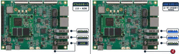
Two USB Modes
-
Default mode: By default, the USB resources are configured in the device tree as 【two USB2.0 HOST channels】 and 【ADB】.
-
USB3.0 mode: If the user requires high-speed USB (such as for industrial cameras) or dual gigabit LAN ports, the USB interface can be made to work in high-speed mode by modifying the kernel source code (device tree).
The USB resource principle block diagram is as follows.
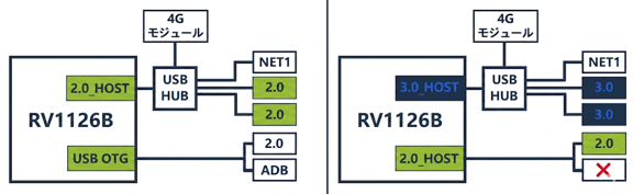
Two USB Modes
💡 Note: When used in USB3.0 mode, the ADB cable must be unplugged. Otherwise, it may cause crosstalk (interference) on 【all】 USB interfaces.
3.2. Switching to USB3.0 Mode
3.2.1 Upgrading to the Latest Firmware
3.2.2 Downloading the Ubuntu System SDK Source Code
For downloading the ubuntu_sdk source code (mainly the kernel source code), refer to “Embedded Low-Level Development/Ubuntu System SDK/Compilation Instructions”.
3.2.3 Modifying the Kernel Device Tree
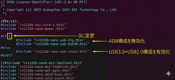
Then, modify the device tree file in the 【kernel source code development repository】 according to the description in the figure below:
Modifying the Kernel Device Tree
- EASY-EAI-Nano-TB device tree entry point: arch/arm64/boot/dts/rockchip/rv1126b-nano.dts
After compilation, a new kernel.img will be generated.
3.2.4 Updating the Kernel Image
Copy the kernel.img generated in the previous step to the rockdev directory of the firmware to replace the original kernel.img, and then write kernel.img to the development board.
3.3. Function Verification and Performance Test
-
USB flash drive for testing: 【USB3.0】Kingston USB flash drive
-
Test interface:
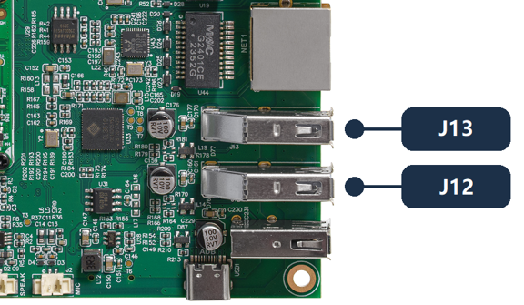
Function Verification and Performance Test
USB Flash Drive Mount Command:
sudo mkdir -p /mnt/usbsudo mount /dev/sda /mnt/usbUSB Flash Drive Test Command - Read:
dd if=/dev/sda of=/dev/null bs=1M count=1000 iflag=direct status=progressUSB Flash Drive Test Command - Write:
dd if=/dev/zero of=/mnt/usb/test.tmp bs=1M count=1000 oflag=direct status=progress3.3.1 USB2.0 Mode
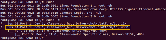
Function Verification:
lsusb -tThere is only one USB2.0 HOST channel with a communication speed of 480M, which is the expected result.
- 1 GB size — Read test: (※ Please refer to the execution result in the original document)
Function Verification:
- 1 GB size — Write test: (※ Please refer to the execution result in the original document)

Function Verification:
3.3.2 USB3.0 Mode
Because ADB cannot be used in USB3.0 mode, use serial-port debugging or SSH debugging to access the board background.
Function Verification:
| lsusb -t |
|---|

Function Verification:
There is one USB2.0 HOST channel with a communication speed of 480M and one USB3.0 HOST channel with a communication speed of 5000M, which is the expected result.
- 1 GB size — Read test (depends on the read/write speed of the USB flash drive): (※ Please refer to the execution result in the original document)

Function Verification photo
- 1 GB size — Write test (depends on the read/write speed of the USB flash drive): (※ Please refer to the execution result in the original document)

Function Verification photo