
Power and System Control Circuit
1. Power ON/OFF Circuit
This circuit controls system power ON/OFF and provides functionality similar to the power button on a smartphone or similar device.
In the current mainboard design, the system is configured to boot directly after power is applied, so operating a physical power button is not required. The PMIC_PWRON signal responsible for power control is routed directly from the internal PMIC (Power Management IC) chip.
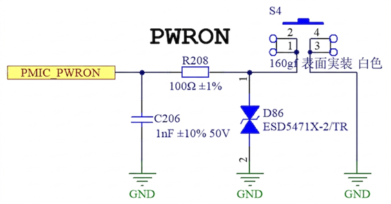
Power ON/OFF Circuit
| Signal Name | Connection Method | Description |
|---|---|---|
| PMIC_PWRON | Pulled up to 5V and directly connected | System power on/off signal |
2. Core Board Power Circuit
The supply voltage for the core board (SoM) is 5V. The standard reference design uses the TMI3255S step-down converter from TMI to provide power. This power IC supports a maximum output current of 5A.
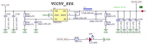
Core Board Power Circuit
💡 Design Recommendation > If you design a custom baseboard and select a different power IC, it is strongly recommended to choose a power IC with an output capability of at least 5A to ensure stable system operation.